Modbus – IAI America ROBO Cylinder Series User Manual
Page 288
6. Modbus
ASCII
280
Modbus
Control Flag Specification Register (CTLF)
Set the method of operation.
If push-motion operation or incremental operation (pitch feed) is selected, set this register every
time a movement command is issued. (This is because the register will be overwritten with the
default value every time the actuator moves.)
CTLF bit structure
Bit 1 (PUSH) = 0: Normal operation (default)
1: Push-motion operation
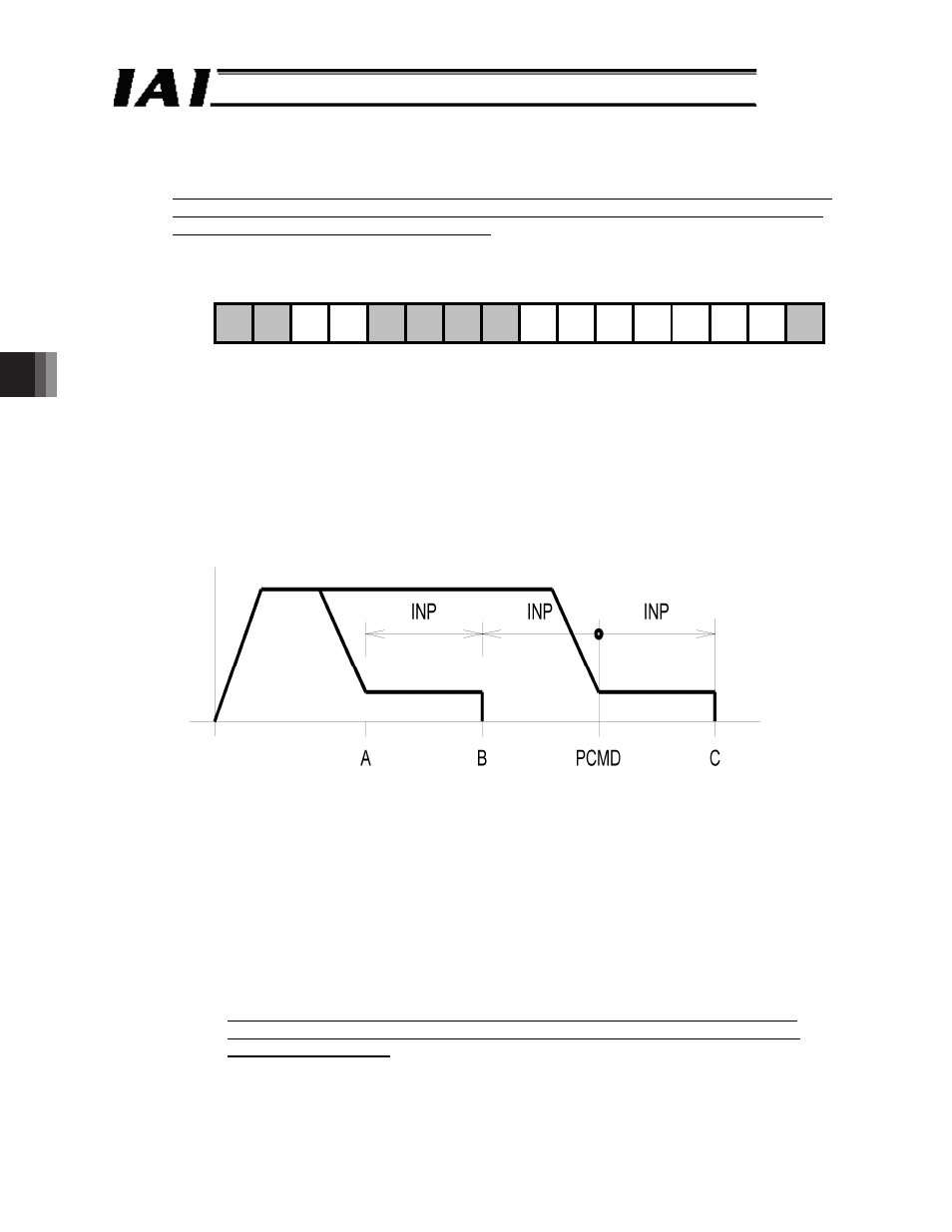
Bit 2 (DIR) =
0: The direction of push-motion operation after completion of approach is
defined as the forward direction (default).
1: The direction of push-motion operation after completion of approach is defined as the
reverse direction.
This bit is used to calculate the direction of final stop position from PCMD. If this bit is set
incorrectly, therefore, the target position will deviate from the specified position by a
distance corresponding to “2 x INP, ” as shown in Fig. 5.3 below.
If bit 1 is set to 0, the setting of this bit is invalid.
Fig. 6.3 Operating Direction in Push-motion Operation
Bit 3 (INC) =
0: Normal operation (default)
1: Incremental operation (pitch feed)
Setting this bit to 1 will enable the actuator to operate relative to the current position.
In this operation, the actuator behaves differently between normal operation and push-
motion operation (CTLF bit 1). While the travel is calculated with respect to the target
position (PCMD) in normal operation, it is calculated relative to the current position in
push-motion operation (when bit 1 = 1).
Here, since relative coordinate calculation involves adding up pulses in mm, followed by
conversion, unlike a calculation method involving addition after pulse conversion,
“repeated relative movements will not cause position deviation as a result of
cumulative errors corresponding to fraction pulses that are not divisible with
certain lead settings”.
Speed
Start position
/5$
.5$
275*
)5. )5. +0% &+4
/1& /1&
06% 06%