Modbus – IAI America ROBO Cylinder Series User Manual
Page 46
4. Communicationn
38
Modbus
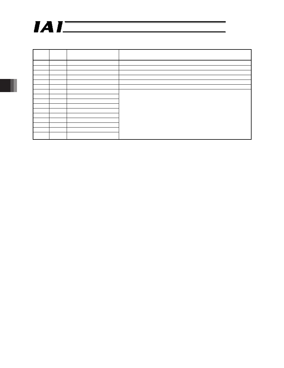
(7) Data of position number specification registers (Address = 0D03
H
) (POSR)
Position movement command register details (Address = 9800
H
) (POSR)
Bit
Symbol
Name
Function
15
-
Cannot be used
14
-
Cannot be used
13
-
Cannot be used
12
-
Cannot be used
11
-
Cannot be used
10
-
Cannot be used
9
PC512 Position command bit 512
8
PC256 Position command bit 256
7
PC128 Position command bit 128
6
PC64
Position command bit 64
5
PC32
Position command bit 32
4
PC16
Position command bit 16
3
PC8
Position command bit 8
2
PC4
Position command bit 4
1
PC2
Position command bit 2
0
PC1
Position command bit 1
These bits indicate position numbers to be moved using binary codes.
Note that the maximum position number varies depending on the model
and PIO pattern.
[When address = 0D03
H
is used]
After specifying a position number, set the CSTR (start signal) of device
control register 1 to 1, and the actuator will move to the specified
position. [Refer to 5.5.1 or 6.6.1.]
[When address = 9800
H
is used]
This register is such that once a position number is specified, the
actuator will move to the specified position. You need not set the CSTR
(start signal).