Modbus – IAI America ROBO Cylinder Series User Manual
Page 198
6. Modbus
ASCII
190
Modbus
6.4.2 Alarm Detail Description Reading <
(1) Function
This bit reads the alarm codes, alarm detail codes and alarm occurrence time that last occurred.
When any alarm is not issued, it is “0
H
”. [Refer to 4.3.2 (1) to (3) for detail]
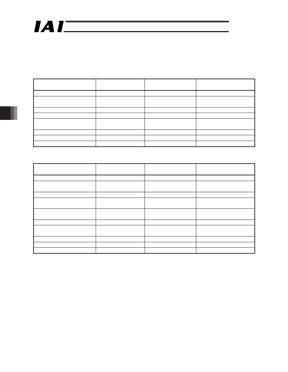
(2) Query format
Field
Number of characters ASCII mode character
string (fixed)
Remarks
Header
1
‘:’
Slave address [H]
2
Arbitrary
Axis number + 1
(01
H
to 10
H
)
Function code [H]
2
‘0’, ‘3’
Register reading
Start address [H]
4
‘0’, ‘5’, ‘0’, ‘0’
Alarm detail code
Number of registers [H]
4
‘0’, ‘0’, ‘0’, ‘6’
Reading addresses 0500
H
to 0505
H
Error check [H]
2
LRC calculation result
Trailer
4
‘CR’, ‘LF’
Total number of bytes
17
(3) Response format
A response message contains 16 bits of data per register.
Field
Number of characters ASCII mode character
string (fixed)
Remarks
Header
1
‘:’
Slave address [H]
2
Arbitrary
Axis number + 1
(01
H
to 10
H
)
Function code [H]
2
‘0’, ‘3’
Register reading
Number of data bytes [H]
2
‘0’, ‘C’
Reading 6 registers = 12
bytes
Data 1 [H]
8
Alarm detail code
Alarm address
Alarm detail code(0500
H
) [Hex]
Alarm address(0501
H
) [Hex]
Data 2 [H]
8
Alarm code
Alarm code [Hex]
Data 3 [H]
8
Alarm occurrence
time
(Note1)
Alarm occurrence time
[Hex]
Error check [H]
2
‘CR’, ‘LF’
Trailer
2
Silent interval
Total number of bytes
35
Note 1 The contents of data differ for the case when the model is equipped with RTC (calendar)
function and RTC is effective [1] and the case when RTC is ineffective or the model is not
equipped with RTC [2].ᴾ
[1] It shows the alarm occurrence time.
[2] It shows the time [msec] passed since the power was
turned on.ᴾ