3 preparation for communication, 1 in case the host uses rs232c interface, Modbus 3 preparation for communication – IAI America ROBO Cylinder Series User Manual
Page 25: Specifications 17, 1) system configuration
3. Specifications
17
Modbus
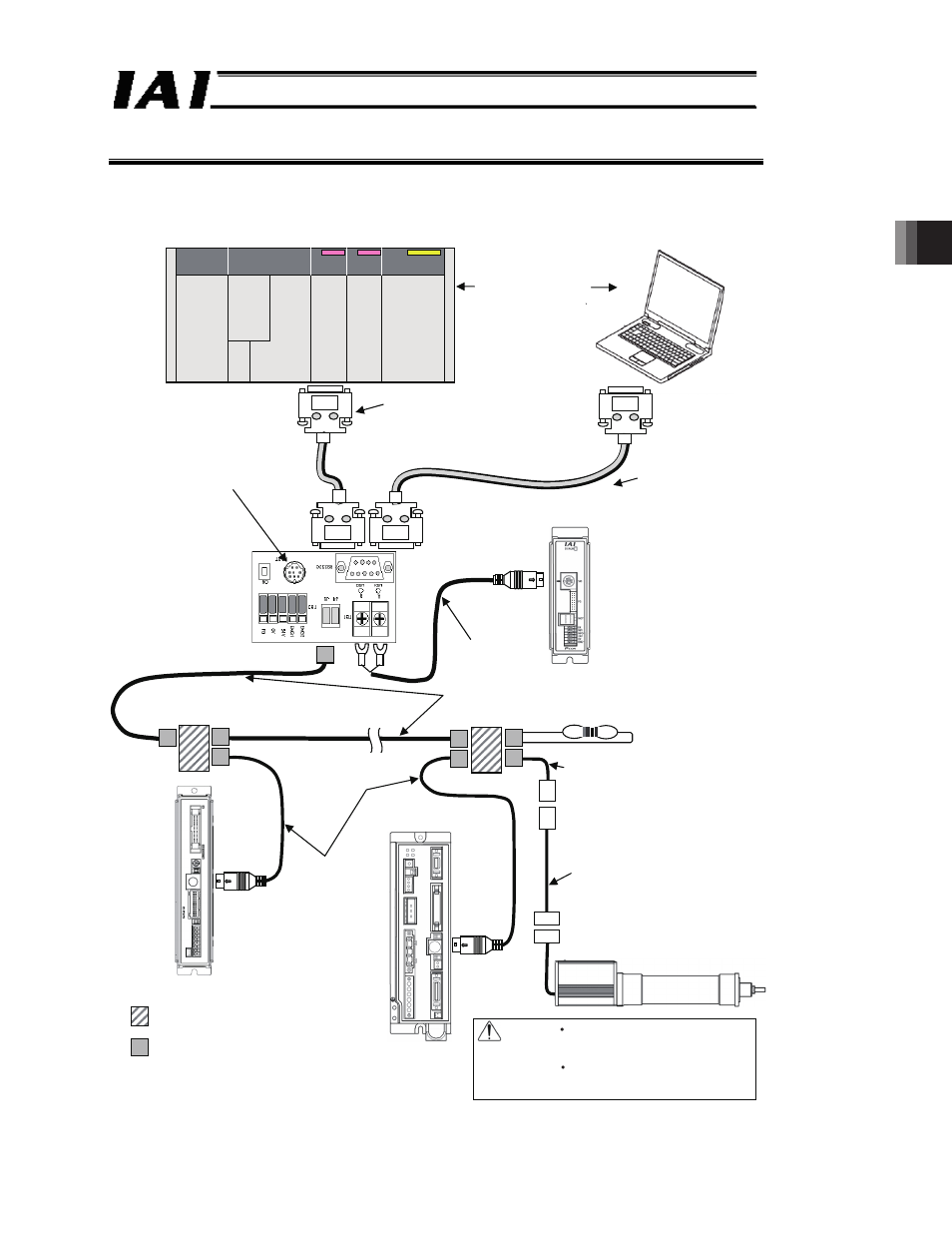
3 Preparation for Communication
3.1 In Case the Host Uses RS232C Interface
(1) System configuration
The host must be either
a PLC or PC. It is not
allowed to connect both
at the same time.
RS232C cable
(prepared by the customer)
Check the pin assignment of the interface
on the host side and prepare either
straight-through or cross-connected cables
accordingly.
(RS232C)
You can connect IAI’s PC
software or other teaching tool.
Vertical specification:
RCB-TU-SIO-A
Horizontal specification:
RCB-TU-SIO-B
(RS232C RS485)
(Female)
⇔
PCON-*
SCON-*
Junction
(5-1473574-4 made by AMP)
e-CON connector
(*-1473562-4 made by AMP)
Can be connected using a
terminal block, instead.
Controller link cables
CB-RCB-CTL002
(Comes with one
junction, one e-CON
connector and one
terminating resistor
with R = 220Ω, 1/4 W)
Fig. 3.1
RS232C cross-connected cable
(prepared by the customer)
PCON-*
(Female)
Mini DIN, 8-pin connector
Recommended cables
(Taiyo Cabletech
HK-SB/20276xL (m) 2P x AWG22)
Prepared by the customer
Terminating resistor R = 220
When using a commercially available
RS232C ⇔ RS485 converter, adjust
the resistance to the converter.
Cable for network connection
CB-ERC2-CTL001
SIO-compatible power supply I/O cable
CB-ERC2-PWBIO***
Caution
Make sure to use the common 0 V
line of the 24 V power supply for
each controller (other than SCON).
For ROBONET connection, refe r to
the separate ROBONET Operation
Manual.
PC
PLC
Master
/host
ERC2 [Refer to Section 3.2 for connection of ERC3]