Modbus – IAI America ROBO Cylinder Series User Manual
Page 152
5. Modbus RTU
144
Modbus
5.4.16 PIO/Modbus Switching Setting <
(1) Function
PIO external command signals can be enabled or disabled.
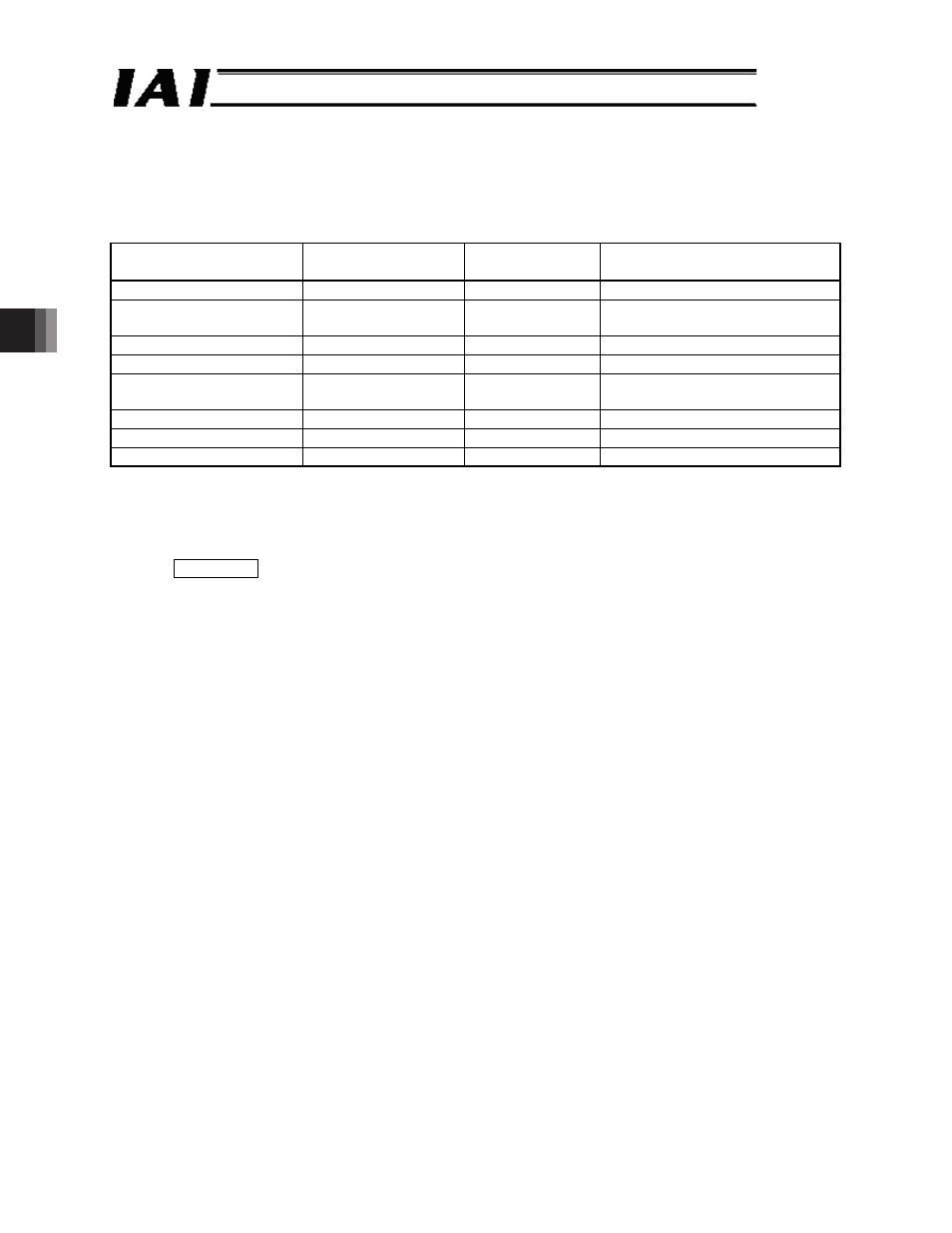
(2) Query format
Field
Number of data items
(number of bytes)
RTU mode
8-bit data
Remarks
Start
None
Silent interval
Slave address [H]
1
Arbitrary
Axis number + 1 (01
H
to 10
H
)
00
H
when broadcast is specified
Function code [H]
1
05
Write to a single coil DO.
Start address [H]
2
0427
PIO/Modbus switching setting
Changed data [H]
2
Arbitrary
*1 Enable Modus commands: FF00
H
Disable Modbus commands: 0000
H
Error check [H]
2
CRC (16 bits)
End
None
Silent interval
Total number of bytes
8
*1 x Enable Modbus commands (ON) (disable PIO command): FF00
H
Operation via PIO signals is not possible.
x
Disable Modbus commands (OFF) (enable PIO command): 0000
H
Operation via external PIO signals is possible.
Supplement If the Modbus command is enabled, the PIO status at change is maintained.
If the Modbus command is switched to disabled, the operation status changes
according to the current PIO status. Note that even if the status of signals that
operate via edge detection has been changed, edge detection is ignored.
(3) Precaution
On a model equipped with an operation mode switch, “Enable PIO commands” will be specified
when the switch is set to the AUTO mode, or “Disable PIO commands” will be specified when
the switch is set to the MANU mode.
On a non-PIO model, the default setting is “Disable PIO commands.”
If IAI’s tool (teaching pendant or PC software) is connected, “Teaching modes 1, 2” and
“Monitor modes 1, 2” are available as tool modes. The correspondence between these modes
and PIO enable/disable specifications are as follows:
“Monitor modes 1, 2” o “Enable PIO commands”
“Teaching modes 1, 2” o “Disable PIO commands”