Modbus, Example 1) – IAI America ROBO Cylinder Series User Manual
Page 166
5. Modbus RTU
158
Modbus
(6) Example of use
Examples of different operations are shown in [1] to [7] below.
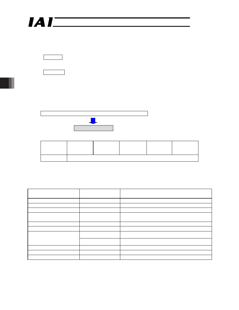
[1] Move by changing the target position. (All data other than the target position are the default
values of their respective parameters.)
Conditions: The operation conditions conform to the default speed, default
acceleration/deceleration and default positioning band set by the controller’s
user parameters. Only the target position is changed to move the actuator.
Supplement: Controller’s user parameters
x
Default speed (parameter No. 8) o Maximum speed of the applicable actuator as
specified in the catalog
x
Default acceleration/deceleration (parameter No. 9) o Rated acceleration of the
applicable actuator as specified in
the catalog
x
Default positioning band (parameter No. 10) o Default value = 0.1 mm
Write the target position specification register (9900
H
)
(Example 1)
Start of movement
(Example 1)
Target position: 50 mm
Target
position
[mm]
Positioning
band
[mm]
Speed
[mm/s]
Acceleration/
deceleration
[G]
Push
[%]
Control flag
50
Need not be set.
ᴾ
Query :01 10 9900 0002 04 0000 1388 38FFᴾ
ᴾ
Response :01 10 9900 0002 6F54
--- The query message is copied, except for the number of bytes and new data, and returned
as a response.
ᴾ
Breakdown of Query Message
Field
RTU mode
8-bit data
Remarks
Start
None
Silent interval
Slave address
01
H
Axis number + 1
Function code
10
H
Start address
9900
H
The starting address corresponds to the setting of
target position specification register 9900
H
.
Number of registers
0002
H
Addresses 9900
H
to 9901
H
are written.
Number of bytes
04
H
2 (registers) × 2 = 4 (bytes) o 4
H
0000
H
All upper bits of the 32-bit data are 0.
New data 1, 2
(target position)
Input unit (0.01 mm)
1388
H
50 [mm] x 100 = 5000 o 1388
H
Error check
38FF
H
CRC checksum calculation result o 38FF
H
End
None
Silent interval
Total number of bytes
13