6 setting controller communication speed, Modbus – IAI America ROBO Cylinder Series User Manual
Page 34
3. Specifications
26
Modbus
3.6 Setting Controller Communication Speed
In order to perform communication, the communication speed of the PLC and each RC
controller must match.
Set the communication speed according to the procedure explained in sections 3.6.1 and 3.6.2.
[For the settings on the host side, refer to the operation manual for your host equipment.]
Please be aware that the wiring is different depending on the system configuration.
3.6.1 Setting Wiring and Hardware for Each System
(1) In case of using a PC as the master (host) controller
It is possible to make settings without changing the current connection. In case of RC
controllers equipped with a mode toggle switch (PCON-C/CG/CF/CA/CFA, ACON-C/CG and
SCON-C/CA), set the mode toggle switch to MANU before making the settings.
(2) In case a PLC is used as the master (host) controller connected via RS232C
Connect a PC as master (host) controller instead of the PLC (refer to Figure 3.1). At this point,
disconnect the PLC from the SIO converter and connect the PC to the teaching port of the
SIO converter [refer to section 3.1 (3)] using the cable supplied with the PC software. In case
of RC controllers with a mode toggle switch (PCON-C/CG/CF/CA/CFA, ACON-C/CG and
SCON-C/CA), set the mode toggle switch to MANU.
(3) In case a PLC is used as the master (host) controller connected via RS485
Connect a PC directly to each RC controller in the same way as for setting axis numbers. In
case of RC controllers with a mode toggle switch (PCON-C/CG/CF/CA/CFA, ACON-C/CG
and SCON-C/CA), set the mode toggle switch to MANU.
(4) When a ROBONET is connected
To set up your ROBONET, connect the cable supplied with your PC software to the teaching
port on the GateWayR unit. Set the MODE selector switch on the GateWayR unit to “MANU.”
3.6.2 Setting Communication Speed
Set the communication speed using the following procedure.
(Note) On ROBONET controllers, the baud rate is set using the ROBONET gateway
parameter setting tool. [For details, refer to the separate ROBONET Operation
Manual.]
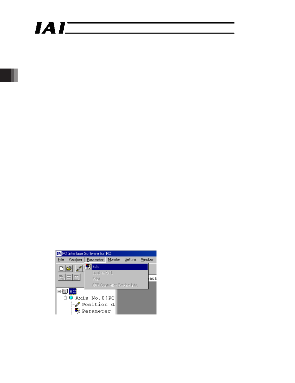
[1] Start the RC connection software and select [Edit (E)] from the [Parameters (P)] menu.
Fig. 3.11