Modbus – IAI America ROBO Cylinder Series User Manual
Page 285
6. Modbus
ASCII
277
Modbus
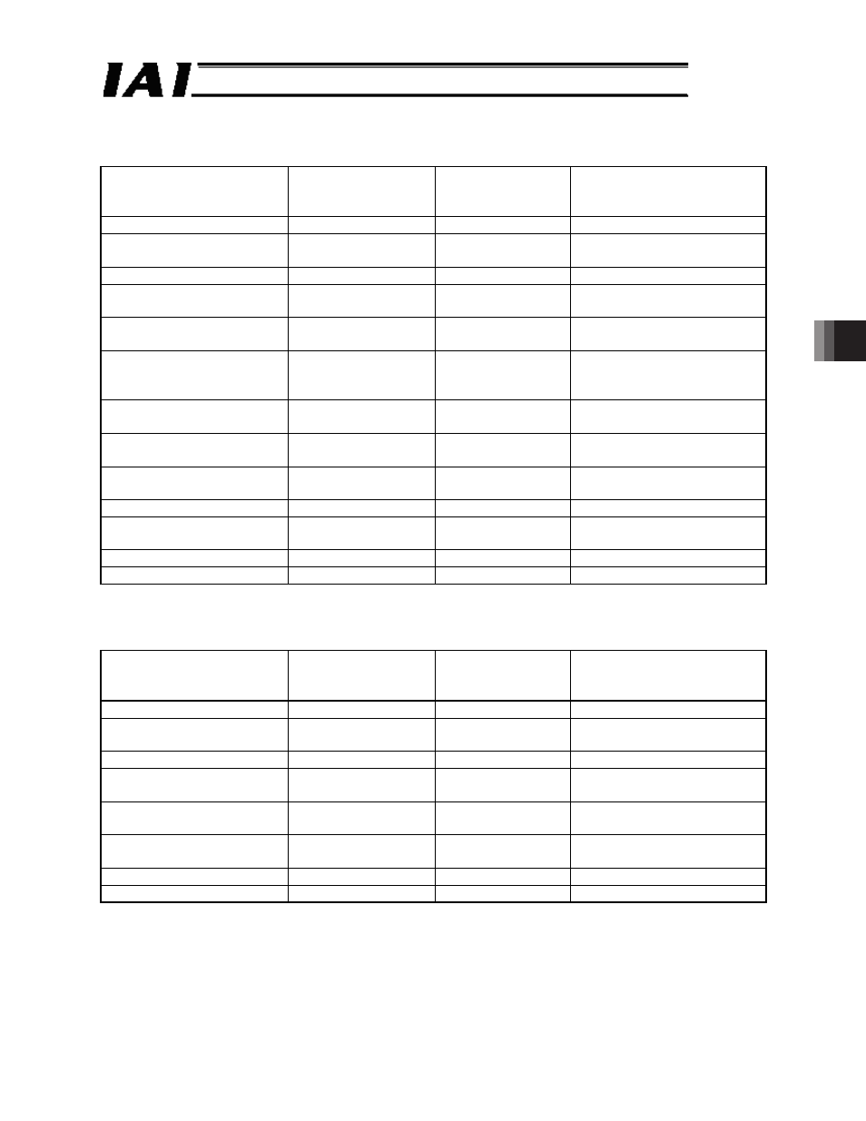
(3) Query format
1 register = 2 bytes = 16-bit data
Field
Number of characters
(number of bytes)
ASCII mode
fixed character
string
Remarks
Header
1
‘:’
Slave address [H]
2
Arbitrary
Axis number + 1 (01
H
to 10
H
)
00
H
if broadcast is specified
Function code [H]
2
‘1’, ‘0’
Numerical value specification
Start address [H]
4
Arbitrary
Refer to 6.7.1. (2), “Start
address list”
Number of registers [H]
4
Arbitrary
Refer to 6.7.1 (2), “Start
address list”
Number of bytes [H]
2
In accordance with
the number of
registers above
Enter the value twice as large
as the number of registers
specified above
Changed data 1 [H]
4
Refer to 6.7.1 (2), “Start
address list”
Changed data 2 [H]
4
Refer to 6.7.1 (2), “Start
address list”
Changed data 3 [H]
4
Refer to 6.7.1 (2), “Start
address list”
:
:
Error check [H]
2
LRC calculation
result
Trailer
2
‘CR’, ‘LF’
Total number of bytes
Up to 256
(4) Response format
When normally changed, the response message responds with a copy of the query message
excluding the number of bytes and changed data.
Field
Number of characters
(number of bytes)
ASCII mode
fixed character
string
Remarks
Header
1
‘:’
Slave address [H]
2
Arbitrary
Axis number + 1 (01
H
to 10
H
)
00
H
if broadcast is specified
Function code [H]
2
‘1’, ‘0’
Numerical value specification
Start address [H]
4
Arbitrary
Refer to 6.7.1 (2), “Start
address list”
Number of registers [H]
4
Arbitrary
Refer to 6.7.1 (2), “Start
address list”
Error check [H]
2
LRC calculation
result
Trailer
2
‘CR’, ‘LF’
Total number of bytes
Up to 256