Modbus – IAI America ROBO Cylinder Series User Manual
Page 274
6. Modbus
ASCII
266
Modbus
6.5.15 Load Cell Calibration Command <
connected.
(1) Function --- SCON-CA only
The dedicated load cell is calibrated.
The factory setting of your load cell is that the ON status corresponds to a no-load state. If you want
to define the reference state as a condition where a work part (load) is installed, calibrate the load
cell.
Also calibrate the load cell in other situations as necessary (readjustment, inspection, etc.).
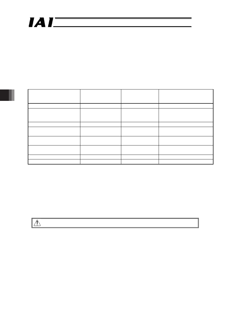
(2) Query format
Field
Number of characters
ASCII mode
character string
(fixed)
Remarks
Header
1
‘:’
Slave address [H]
2
Arbitrary
Axis number + 1 (01
H
to 10
H
)
00
H
when broadcast is
specified
Function code [H]
2
‘0’, ‘5’
Write to a single coil DO
Start address [H]
2
‘0’, ‘4’ ‘2’, ‘6’
Load cell calibration
command
Changed data [H]
2
Arbitrary
Calibration command: FF00
H
Normal operation: 0000
H
Error check [H]
2
LRC calculation
result
Trailer
2
‘CR’, ‘LF’
Total number of bytes
17
(3) Calibration procedure
[1] Stop the actuator operation. (The load cell cannot be calibrated while the actuator is
performing any axis operation or push-motion operation or being paused, in which case 0E1
(load cell calibration error) alarm generates.)
[2] Turn this signal ON and keep it ON for at least 20 ms.
[3] When the calibration is complete, the calibration complete signal (CEND of device status
register 1 explained in 4.3.2 (12)) turns ON. After confirming that the CEND has turned ON,
turn OFF the CLBR.
If the calibration was unsuccessful, a 0E1 (load cell calibration error) alarm generates.
Caution: Normal operation commands are not accepted while the CLBR is ON.