5 setting axis numbers, Modbus – IAI America ROBO Cylinder Series User Manual
Page 33
3. Specifications
25
Modbus
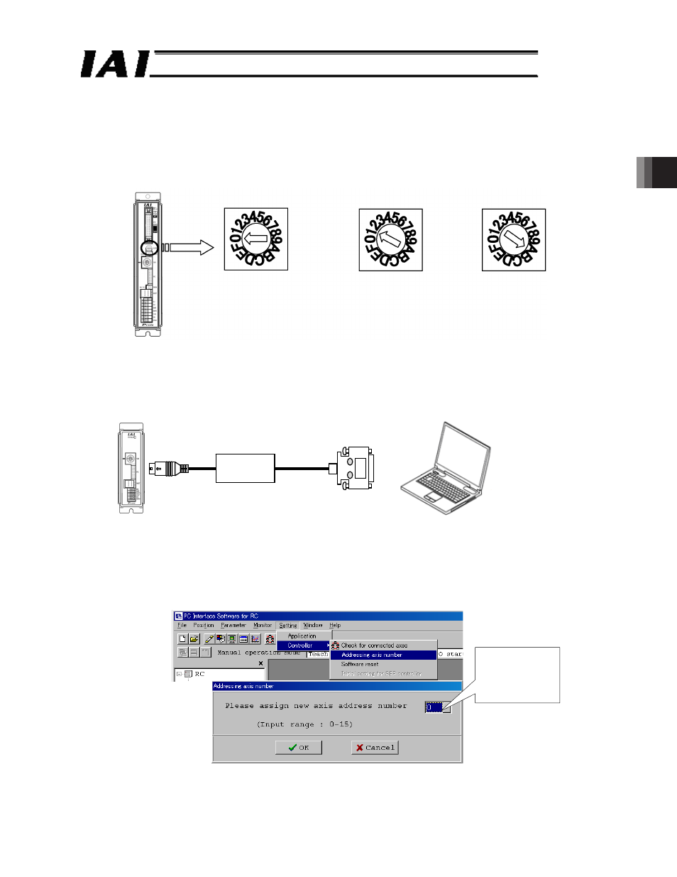
In case of axis 1
(* set the switch to 0)
In case of axis 2
(* set the switch to 1)
In case of axis 11
(* set the switch to A)
3.5 Setting Axis Numbers
Set an axis number for each RC controller on the SIO link using hexadecimal digits from 0 to
F
H
, which is the number for the 16th axis.
If the panel surface of an RC controller has an axis number setting switch (ADRS) (PCON-
C/CG/CF/CA/CFA, ACON-C/CG, SCON-C/CA and ROBONET), adjust the arrow to point to
the axis number using a flat bladed screwdriver (make sure that each axis number is unique).
Fig. 3.8
On RC controllers having no axis number setting switches, use the PC software or other teaching
pendant to set the axis number. In this example, how to set the axis number using the PC
software is explained. [For information on how to set the axis number using your teaching
pendant, refer to the operation manual for each (CON-PTA, CON-PT, CON-T, RCM-E, RCM-T)].
Connect the PC to the SIO connector of the RC controller for which an axis number is to be set.
Fig. 3.9
Set the numbers using the following procedure.
[1] Start the RC connection software and select the [Setting] menu.
[2] Select the [Controller Setting)] menu item.
[3] Select the [Axis Number Assignment (N)] menu item.
[4] Input the axis numbers (0 to 15) to the axis number table with a care not to make duplication.
Fig. 3.10
RS232C
RS485
PC
Enter the value
obtained by
subtracting 1 from
the axis number to
be set.