Modbus – IAI America ROBO Cylinder Series User Manual
Page 182
5. Modbus RTU
174
Modbus
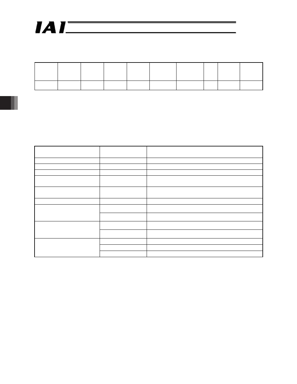
(6) Sample query
A sample query that rewrites all data of position No. 12 of axis No. 0 is shown below.
Axis No. 0
Target
position
(mm)
Positioning
band
(mm)
Speed
(mm/sec)
Individual
zone
boundary+
(mm)
Individual
zone
boundary-
(mm)
Acceleration
(G)
Deceleration
(G)
Push
(%)
Threshold Movement
control
100
0.1
200
60
40
0.01
0.3
0
0
Normal
movement
Query (silent intervals are inserted before and after the query)
01 10 10 C0 00 0F 1E 00 00 27 10 00 00 00 0A 00 00 4E 20 00 00 17 70 00 00 0F A0 00 01
00 1E 00 00 00 00 00 00 70 1E
Received response 01 10 10 C0 00 0F 84 F1
--- The query message is copied, except for the number of bytes and new data, and returned
as a response.
ᴾ
Breakdown of Query Message
Field
RTU mode
8-bit data
Remarks
Start
None
Silent interval
Slave address
01
H
Axis No. 0 + 1
Function code
10
H
Start address
10C0
H
The start address is the target position specification
register 10C0
H
for position No. 12. *1
Number of registers
000F
H
Total 15 registers of register symbols PCMD to
CTLF are specified to be written.
Number of bytes
1E
H
15 (registers) x 2 = 30 (bytes) o 1E
H
0000
H
All upper bits of the 32-bit data are 0.
New data 1, 2
(target position)
Input unit (0.01 mm)
2710
H
100 (mm) x 100 = 10000 o 2710
H
0000
H
All upper bits of the 32-bit data are 0.
New data 3, 4
(positioning band)
Input unit (0.01 mm)
000A
H
0.1 (mm) x 100 = 10 o 000A
H
0000
H
All upper bits of the 32-bit data are 0.
4E20
H
200 (mm/sec) x 100 = 20000 o 4E20
H
New data 5, 6 (speed)
Input unit (0.01 mm/sec)
0FA0
H
40 (mm) x 100 = 4000 o 0FA0
H
Continue to the next page