Modbus – IAI America ROBO Cylinder Series User Manual
Page 282
6. Modbus
ASCII
274
Modbus
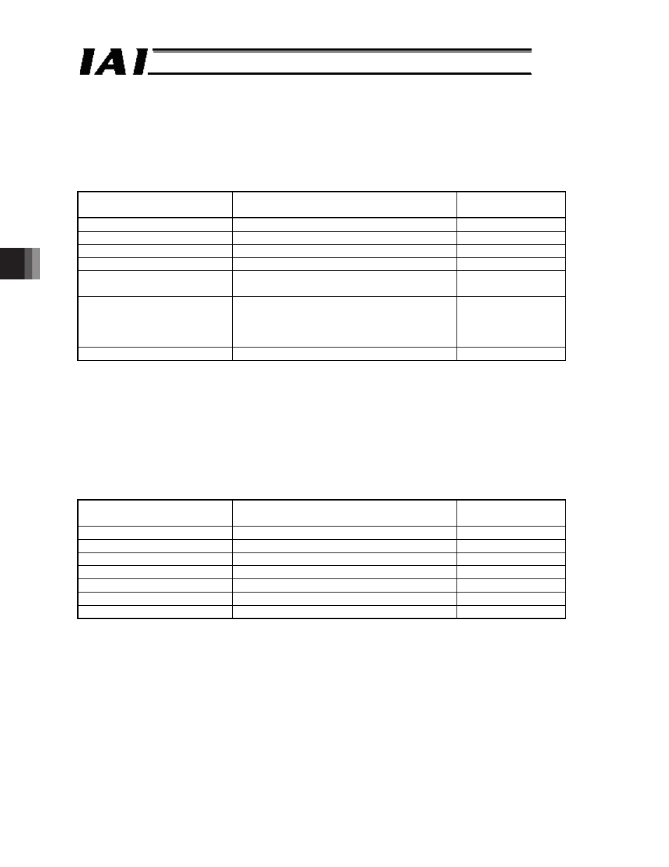
(5) Query sample
Examples of different operations are shown in [1] to [3] below.
[1] A sample query that turns the servo of a controller of axis No. 0 on and then executes home
return operation is performed.
Query
First time
01 06 0D 00 10 00 DC --- Servo ON
Second time 01 06 0D 00 10 10 CC --- Home return
Field
ASCII mode 8-bit data
Converted ASCII
code data [H]
Start
‘:’
3A
Slave address [H]
‘0’, ‘1’
3031
Function code [H]
‘0’, ‘6’
3036
Start address [H]
‘0’, ‘D’, ‘0’, ‘0’
30443030
Changed data [H]
First time: ‘1’, ‘0’, ‘0’, ‘0’
Second time: ‘1’, ‘0’, ‘1, ‘0’
31303030
31303130
Error check [H]
First time: ‘D’, ‘C’ (in accordance with CRC
calculation)
Second time: ‘C’, ‘C’ (in accordance with
CRC calculation)
4443
4343
End
‘CR’, ‘LF’
0D0A
Note 1 Home return is not performed even if 1010
H
is sent to change the data while the servo is
OFF (refer to the timing chart at startup of each RC controller).
Note 2 To keep the previous status, send the previous status even if there is no change. As in the
example above, keep the servo ON bit as 1 at home return as well.
If the change is successful, the response message will be the same as the query.
[2] Move to position No. 1 using the position movement specification register (address 9800
H
).
Before this operation, perform the operation in example [1] above to complete a home return.
Query (Silent intervals are inserted before and after the query.)
01 06 98 00 00 01 60
Field
ASCII mode 8-bit data
Converted ASCII
code data [H]
Start
‘:’
3A
Slave address [H]
‘0’; ‘1’
3031
Function code [H]
‘0, ’ ‘6’
3036
Start address [H]
‘9’, ‘8’, ‘0’, ‘0’
39383030
Changed data [H]
‘0’, ‘0’, ‘0’, ‘1’
30303031
Error check [H]
‘6’, ‘0’ (in accordance with CRC calculation) 3630
End
‘CR’, ‘LF’
0D0A