Modbus – IAI America ROBO Cylinder Series User Manual
Page 165
5. Modbus RTU
157
Modbus
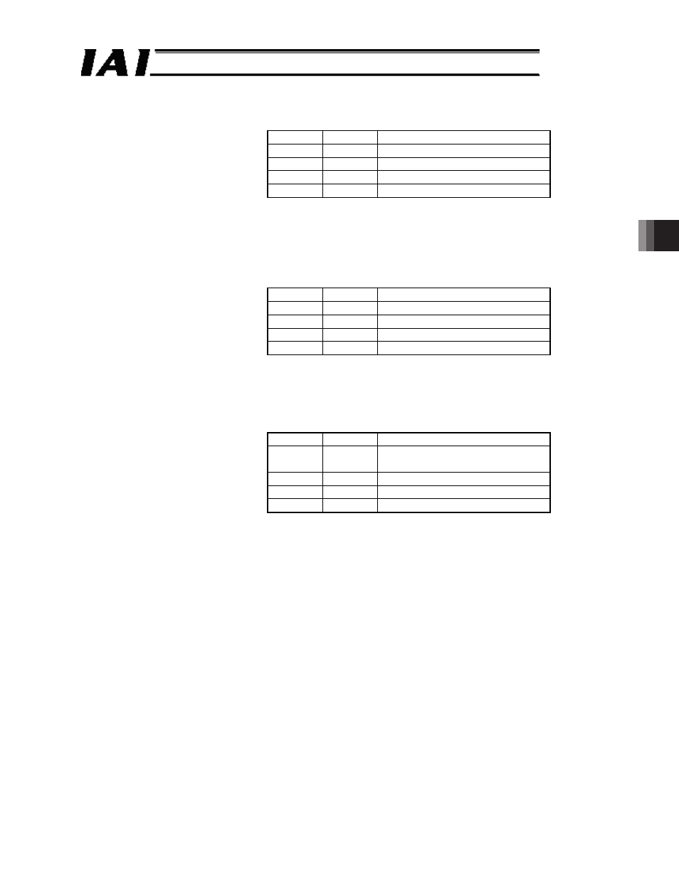
Bit 4 (GSL0), 5 (GSL1) = Refer to the table below. (These bits can be set only on SCON-CA
controllers.)
GSL1
GSL0
Function
0
0
Select parameter set 0 (default).
0
1
Select parameter set 1
1
0
Select parameter set 2
1
1
Select parameter set 3
You can register a maximum of four servo gain parameter sets consisting of
six parameters and move the actuator to each position by selecting a different
parameter set every time. [For details, refer to the operation manual for your
controller.]
Bit 6 (MOD0), 7 (MOD1) = Refer to the table below. These bits cannot be set on PCON-* and
ERC2 controllers.)
MOD1
MOD0
Function
0
0
Trapezoid pattern (default)
0
1
S-motion
1
0
Primary delay filter
1
1
Cannot be used.
These signals are used to select the acceleration/deceleration pattern
characteristics. Set one of the patterns before issuing an actuator movement
command. [For details, refer to the operation manual for your controller.]
Bit 12 (NTC0), 13 (NTC1) = Refer to the table below. (These bits can be set only on SCON-CA
controllers.)
NTC1
NTC0
Function
0
0
Do not use vibration control
(default).
0
1
Select parameter set 1
1
0
Select parameter set 2
1
1
Select parameter set 3
When vibration control is used, you can register a maximum of three
parameter sets and move the actuator to each position by selecting a different
parameter set every time. [For details, refer to the operation manual for your
controller.]