Modbus – IAI America ROBO Cylinder Series User Manual
Page 306
6. Modbus
ASCII
298
Modbus
(6) Sample query
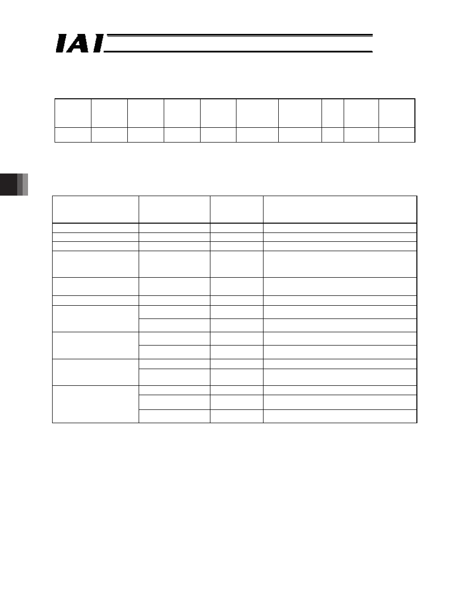
A sample query that rewrites all data of position No. 12 of axis No. 0 is shown below.
Axis No. 0
Target
position
(mm)
Positioning
band
(mm)
Speed
(mm/sec)
Individual
zone
boundary+
(mm)
Individual
zone
boundary-
(mm)
Acceleration
(G)
Deceleration
(G)
Push
(%)
Threshold Movement
control
100
0.1
200
60
40
0.01
0.3
0
0
Normal
movement
Query 01 10 10C0 000F 1E 0000 2710 0000 000A 0000 4E20 0000 1770
0000 0FA0 0001 001E 0000 0000 0000 EE[CR][LF]
Received response 01 10 10C0 000F 10[CR][LF]
ᴾ
Breakdown of Query Message
Field
ASCII mode
fixed character
string
Converted
ASCII code
data [H]
Remarks
Header
‘:’
3A
Slave address
‘0’, ‘1’
3031
Axis No. 0 + 1
Function code
‘1’, ‘0’
3130
Start address
‘1’, ‘0’, ‘C’, ‘0’
31304330
The start address is the target position
specification register 10C0
H
for position No.
12. *1
Number of registers
‘0’, ‘0’, ‘0’, ‘F’
30303046
Total 15 registers of register symbols
PCMD to CTLF are specified to be written.
Number of bytes
‘1’, ‘E’
3145
15 (registers) x 2 = 30 (bytes) o 1E
H
‘0’, ‘0’, ‘0’, ‘0’
30303030
All upper bits of the 32-bit data are 0.
New data 1, 2
(target position)
Input unit (0.01 mm)
‘2’, ‘7’, ‘1’, ‘0’
32373130
100 (mm) x 100 = 10000 o 2710
H
‘0’, ‘0’, ‘0’, ‘0’
30303030
All upper bits of the 32-bit data are 0.
New data 3, 4
(positioning band)
Input unit (0.01 mm)
‘0’, ‘0’, ‘0’, ‘A’
30303041
0.1 (mm) x 100 = 10 o 000A
H
‘0’, ‘0’, ‘0’, ‘0’
30303030
All upper bits of the 32-bit data are 0.
New data 5, 6 (speed)
Input unit (0.01
mm/sec)
‘4’, ‘E’, ‘2’, ‘0’
34453230
200 (mm/sec) x 100 = 20000 o 4E20
H
‘0’, ‘0’, ‘0’, ‘0’
30303030
All upper bits of the 32-bit data are 0.
‘1’, ‘7’, ‘7’, ‘0’
31373730
60 (mm) x 100 = 6000 o 1770
H
New data 7, 8
(individual zone
boundary +)
Input unit (0.01 mm)
‘0’, ‘F’, ‘A’, ‘0’
30464130
40 (mm) x 100 = 4000 o 0FA0
H
Continue to the next page