Chapter 4 operationg part 1 installation 58, Part 1 installation, 2] timing chart – IAI America ASEL User Manual
Page 80
Chapter 4 Operationg
Part 1 Installation
58
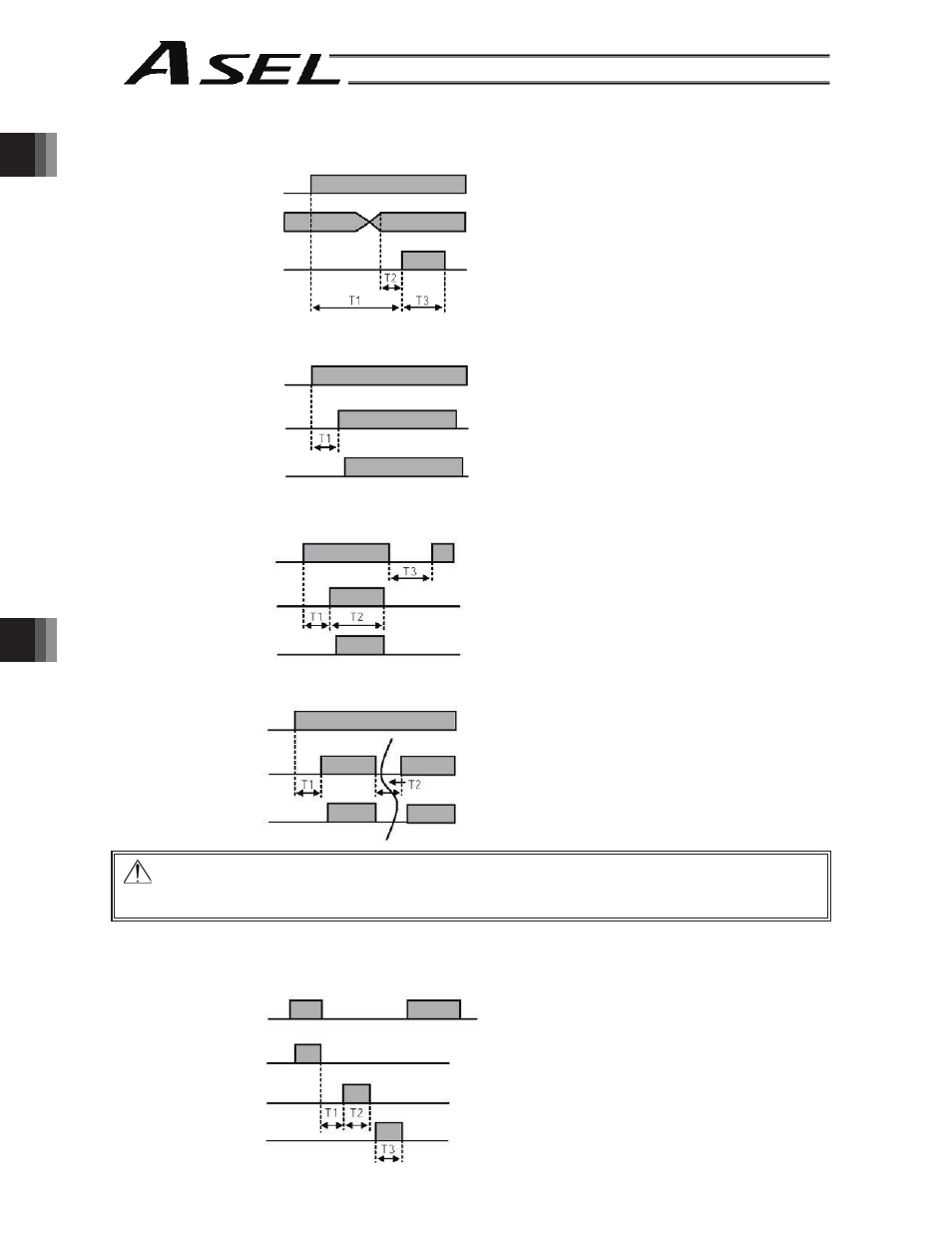
Program 1
Program 2
T1: Duration after the ready output turns ON until
input of external start signal is permitted
T1 = 10 msec min.
T2: Duration after the program number is input
until input of external start signal is permitted
T2 = 50 msec min.
T3: Input duration of external start signal
T3 = 100 msec min.
T1: Time after the ready output turns ON until the
auto-start program start signal can be input to
input port No. *
T1 = 10 msec min.
* Auto program start:
Set “0” in other parameter No. 7, “Auto program
start setting.”
T1: T1: Time after the ready output turns ON until
input function specification value 3 (soft reset
signal) can be input to input port No. *
T1 = 10 msec min.
T2: T2: Time until the soft reset signal becomes
effective
T2 = 1 sec min.
T3: Time after the soft reset signal is cancelled
until the ready signal is output
T1: Time after the ready output turns ON until input
function specification value 4 (servo ON signal)
can be input to input port No. *
T1 = 10 msec min.
T2: Interval after the servo is turned OFF until it is
turned ON again
T2 = 1.5 sec min.
T1: Time after the emergency stop input is reset until
the drive-source cutoff reset signal can be input.
T1 = 2 sec min.
T2: Time during which the drive-source cutoff reset
signal is input
T1 = 10 msec min.
T3: Time during which the pause reset signal is input
T1 = 10 msec min.
Warning : Turning the servo ON near the mechanical end may disturb the magnetic pole phase detection,
and may cause the magnetic pole unconfirmed error or the magnetic pole detection error.
Put the slider or rod away from the mechanical end when turning the servo ON.
Part 1 Installation
Ready output
Program number
input
External start
input
Ready output
Auto-start program
start signal input
Auto program
start
Ready output
Soft reset signal
input
Program starting
Ready output
Servo ON signal
input
Servo ON
Program starting
Emergency stop
Drive-source
cutoff reset
Pause reset
[2] Timing chart
[1] Program start
[2] Auto program start
* Set input function specification value 5 (auto-start program start signal) for input port No. *.
[3] Soft reset signal
* Set input function specification value 3 (soft reset signal) for input port No. *.
[4] Servo ON signal
* Set input function specification value 4 (servo ON signal) for input port No. *.
[5] When the recovery type after emergency stop or enable operation is set to “Operation continued”
* Set other parameter No. 10 to “2,” and set input function specification value 7 (operation-pause reset signal) for input port
No. *. Set input function specification value 17 (drive-source cutoff reset input signal) for other input port No. *.