IAI America ASEL User Manual
Page 37
Part 1 Installation
Chapter 2 Specifications
15
Part 1 Installation
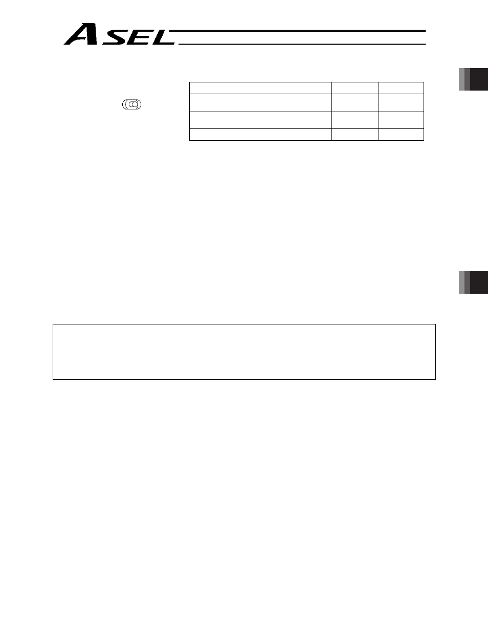
[10] MANU/AUTO switch:
This switch is used to specify the controller operation mode.
MANU
AUTO
Teaching pendant/PC software operation
(When the teaching connector is used)
Possible
Not possible
PC software operation (when the USB
connector is used)
Possible
Note)
Not possible
Starting of an auto start program
Not possible
Possible
Note) When this switch is set to the “MANU” side and the USB
connector is used, the servo cannot be turned on unless a
dummy plug or teaching pendant is connected to the TP
connector. When the USB connector is used, always keep
a dummy plug or PC software cable connected to the TP
plug while the controller is in use. (This is to cancel the
disabled condition.)
If a dummy plug is used, always operate the controller in a
condition where the emergency stop switch is within an
easy reach.
[11] USB connector:
This connector is used to connect the PC software and the
controller via a USB cable.
Connector:
USB connector B (XM7B-0442)
Connected to: USB cable
The maximum USB cable length is 5 m.
Note
y
When the USB port is used, the USB driver contained in the “X-SEL PC Software IA-101-X-USB” CD-
ROM must be installed by connecting all applicable controllers one by one. For the driver installation
method, refer to the X-SEL PC Software Operation Manual.
y
When the USB port is used, a dummy plug must be connected to the teaching connector [12].
Dummy plug model: DP-3
MANU
AUTO
(left)
(right)