IAI America ASEL User Manual
Page 412
Appendix
List of Parameters
390
Appendix
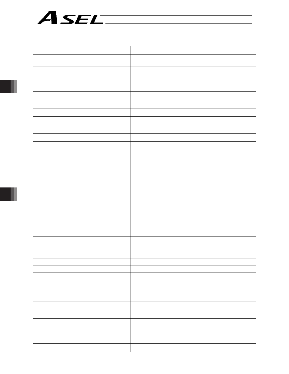
Driver parameters
No.
Parameter name
Default value
(Reference)
Input range
Unit
Remarks
29
Motor/encoder characteristic word
(compatible with E, priority on E)
(configuration information)
0000H
Reference
only
For adjustment by the manufacturer
30
Motor/encoder control word 1
(compatible with E, priority on E)
(configuration information)
5000
Reference
only
0.1 K (Kelvin =
temperature unit)
For adjustment by the manufacturer
31
Motor/encoder control word 2
(compatible with E, priority on E)
(configuration information)
0000H
Reference
only
For adjustment by the manufacturer
32
Motor/encoder control word 3
(configuration information)
(encoder cable length) [m]
2
1 ~ 30
Encoder cable length (m)
If the encoder has been replaced, don’t
forget to change the setting of this
parameter.
33
Motor/encoder control word 4
(configuration information)
14H
Reference
only
For adjustment by the manufacturer
34
Motor/encoder control word 5
(configuration information)
0000H
Reference
only
For adjustment by the manufacturer
35
(Configuration information)
0000H
Reference
only
For adjustment by the manufacturer
36
(Configuration information)
0000H
Reference
only
For adjustment by the manufacturer
37
(Configuration information)
0000H
Reference
only
For adjustment by the manufacturer
38
Push torque limit at positioning
70
0 ~ 70
%
39
Push torque limit at home return
120
0 ~ 150
%
40
Maximum torque limit
300
10 ~ 400
%
*The maximum value that can be set varies
depending on the motor, etc.
41
Dynamic brake operation
specification
0
0 ~ 1
(Data for other model)
42
Software DB operation
specification
0
0 ~ 1
0: Disable, 1: Enable
43
Speed loop proportional gain
500
1 ~ 32767
Proportional gain
44
Speed loop integral gain
1667
1 ~ 3276700
Integral gain
45
Torque filter time constant
0
0 ~ 2500
46
Current control band number
4
0 ~ 4
47
Current ON time for excited-
phase signal detection step
128
0 ~ 32767
ms
48
Excited-phase signal detection
method
1
0 ~ 2
0: Current suppression method
1: Distance suppression method
2: Distance suppression method (300%
excitation) (Main application version
0.10 or later)
49
Excited-phase signal detection
direction
0
0 ~ 1
0: CW, 1: CCW
50
Excited-phase fixed mode:
Torque-limit switching type
0
0 ~ 1
(Data for other model)
51
Excited-phase fixed mode:
Torque limit
0
0 ~ 100
%
(Data for other model)
52
(For expansion)
0H
0000H ~
FFFFH
53
Current control word 1
0H
Reference
only
54
Current control word 2
0H
Reference
only
The factory setting conforms to the standard
specification of the actuator.
The home return torque becomes higher as
the value gets larger.
This does not usually need a change,
however, it may be necessary to make the
value larger when the home return
operation completes before reaching the
proper position due to increase of slider
resistance depending on the way to mount
or the condition of load in vertical oriented
mounting.
Setting Reference: Set value = 120% (when
direction of home return is upwards) to 80%
(when direction of home return is
downwards)