IAI America ASEL User Manual
Page 79
Part 1 Installation
Chapter 4 Operation
57
Part 1 Installation
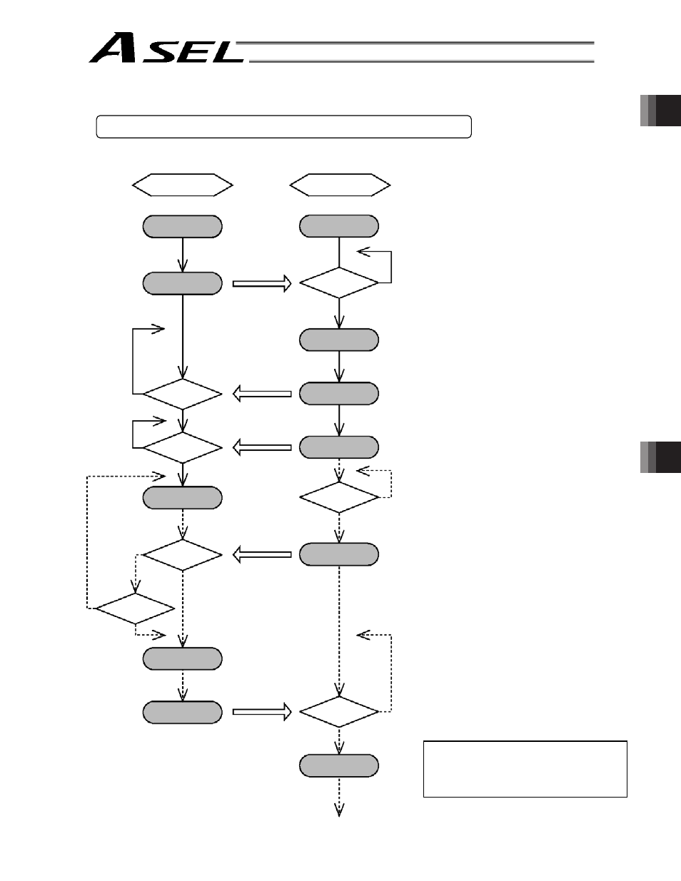
Note) The assignments of dedicated
input/output port functions (such
as RDY output start signal)
reflect the factory settings.
Controller
Power ON
READY signal ON
Program number
confirmed?
N
N
N
N
Y
Y
Y
N
N
Y
N
Y
Start signal
confirmed?
Program run
Emergency-stop
signal confirmed?
Controller
error?
Servo OFF
ALARM signal ON
Alarm output
Emergency-stop
input
External start input
Program number
input
Ready output
External device
Power ON
READY signal
confirmed?
Various I/O
processing
Program number
specification
Start signal ON
Emergency-stop
switch ON?
Emergency-stop
signal ON
ALARM signal
confirmed?
ALARM
processing
Y
Y
3.2
Starting via External Signal Selection
(1) Flow chart
When the READY signal (Output
port No. 301) turns ON, the RDY
lamp (green) on the controller front
panel will illuminate.
Input a desired program number as
a BCD code from the external
device (Input port Nos. 16 through
22).
Input a start signal (input port No. 0)
from the external device.
If the optional panel unit is
connected, the CODE display area
indicates the program number of
each program that has been
started.
If an emergency-stop signal was
input from the external device or a
controller error occurred, the
controller will turn off the servo
power. (The RDY lamp will turn
off.)
Select a desired program number externally and then input a start signal.