I/o interface list – IAI America ASEL User Manual
Page 350
Part 3 Positioner Mode
Chapter 5 T
eaching Mode
328
Part 3 Positioner Mode
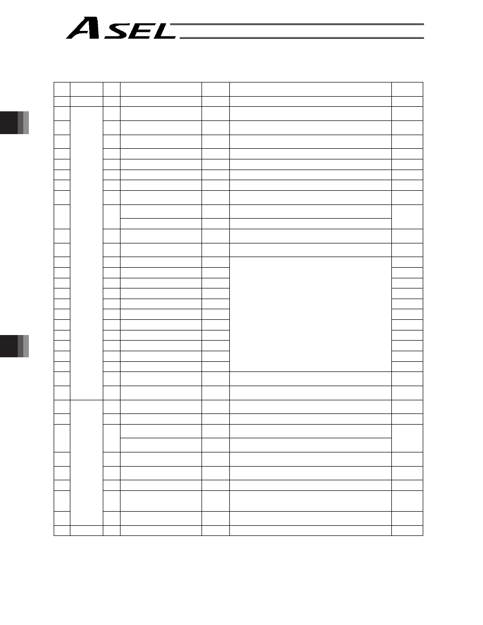
1. I/O Interface List
Pin
No. Category
Port
No.
Signal name
Signal
symbol
Function overview
Cable
color
1A
P24
External power supply 24 V
P24
1-Brown
1B
016 Axis 1 jog-
JOG1-
Axis 1 will move in the negative direction while this signal is
ON.
1-Red
2A
017 Axis 2 jog+
JOG2+
Axis 2 will move in the positive direction while this signal is
ON.
1-Orange
2B
018 Axis 2 jog-
KPG2-
Axis 2 will move in the negative direction while this signal is
ON.
1-Yellow
3A
019 Inching (0.01 mm)
1C001
“0.01 mm” is specified as the inching distance.
1-Green
3B
020 Inching (0.1 mm)
1C01
“0.1 mm” is specified as the inching distance.
1-Blue
4A
021 Inching (0.5 mm)
1C05
“0.5 mm” is specified as the inching distance.
1-Purple
4B
022 Inching (1 mm)
1C1
“1 mm” is specified as the inching distance.
1-Gray
5A
023 Error reset
RES
Present alarms will be reset at the leading edge of this
signal.
1-White
Start
CSTR
The actuator will start moving at the leading edge of this
signal.
5B
000
Current position write
PWRT
The current position is written in the teaching mode.
1-Black
6A
001 Servo ON
SON
The servo will remain on while this signal is ON, and remain
off while this signal is OFF.
2-Brown
6B
002 *Pause
*STP
The actuator can be moved when this signal is ON, and will
decelerate to a stop when the signal turns OFF.
2-Red
7A
003 Position input 1
PC1
2-Orange
7B
004 Position input 2
PC2
2-Yellow
8A
005 Position input 3
PC3
2-Green
8B
006 Position input 4
PC4
2-Blue
9A
007 Position input 5
PC5
2-Purple
9B
008 Position input 6
PC6
2-Gray
10A
009 Position input 7
PC7
2-White
10B
010 Position input 8
PC8
2-Black
11A
011 Position input 9
PC9
3-Brown
11B
012 Position input 10
PC10
3-Red
12A
013 Position input 11
PC11
Input the position number corresponding to the position
you want to move the actuator to.
Be sure to specify a position input by no later than 6 msec
before the start input signal turns ON.
Position numbers are input as binary codes (factory
setting).
In the teaching mode, specify the position number for
which the current position will be written.
Position numbers are input as binary codes (factory
setting).
3-Orange
12B
014 Teaching mode specification MODE
ON: Teaching mode
OFF: Positioner mode
3-Yellow
13A
Input
015 Axis 1 jog+
JOG1+
Axis 1 will move in the positive direction while this signal is
ON.
3-Green
13B
300 *Alarm
*ALM
This signal remains ON if the controller is normal. It will turn
OFF if an alarm occurs.
3-Blue
14A
301 Ready
RDY
This signal will turn ON when the controller becomes ready. 3-Purple
Positioning complete
PEND
This signal will turn ON once the actuator has moved to the
target position and entered the positioning band.
14B
302
Write complete
WEND This signal will turn ON when writing of position data is
completed.
3-Gray
15A
303 Home return complete
HEND
This signal is OFF when the power is input, and will turn ON
when home return is completed.
3-White
15B
304 Servo ON output
SVON
This signal will turn ON when the servo is turned on, and
turn OFF when the servo is turned off.
3-Black
16A
305 Teaching mode output
TCMD
This signal will remain ON during the teaching mode.
4-Brown
16B
306 System battery error
SSER
This signal will turn ON when the voltage of the system-
memory backup battery drops to the voltage-low warning
level.
4-Red
17A
Output
307 Absolute battery error
ABER
This signal will turn ON when the voltage of the absolute-
data backup battery drops to the voltage-low warning level. 4-Orange
17B
N
External power supply 0 V
N
4-Yellow
*: Contact B (always ON)