Parameters, Details of each input signal – IAI America ASEL User Manual
Page 361
Part 3 Positioner Mode
Chapter 6 DS-S-C Compatible Mode
339
Part 3 Positioner Mode
2. Parameters
To use the controller in the DS-S-C1 compatible mode, set other parameter No. 25 to “16.”
Other parameter No. 25 = 16, “DS-S-C1 compatible mode”
3. Details of Each Input Signal
Start (CSTR)
The actuator will start moving to the position corresponding to the specified position data upon detection of
the OFF o ON leading edge of this signal. Position numbers are specified using a 13-bit BCD code
consisting of PC1 through 1000.
Before movement is started, the target position, speed and acceleration/deceleration must be set as
position data. Use a PC (software) or teaching pendant to set position data.
Turn on the power, specify position No. 0 (PC1 through 1000 are all OFF) and then turn this signal ON,
and the actuator will start home return.
If a movement command is executed when no single home-return operation has been performed after the
power was input, “C6F, Home-return incomplete error” will generate.
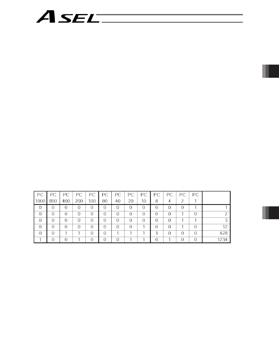
Position Nos. 1 through 1000 (PC1 through 1000)
When a movement command is executed upon OFF o ON of the start signal, the controller will load the
command position number specified by the 13-bit BCD code consisting of PC1 through 1000.
A desired position number between 1 and 1500 can be specified. Specify the one’s place in PC1 through
8, ten’s place in PC10 through 80, hundred’s place in PC100 through 800, and thousand’s place in
PC1000.
An example of position number specification based on ON/OFF levels of PC1 through 1000 is shown
below.
Pause (STP)
If this signal turns ON while the actuator is moving, the controller will cause the actuator to decelerate to a
stop.
The remaining travel distance will be held, which means that when the signal turns OFF again, the
actuator will resume movement of the remaining travel distance.
To cancel the movement command altogether after turning ON the pause signal, turn ON the cancellation
signal while this signal is ON to cancel the remaining travel distance.
The pause signal can be used for the following purposes:
[1] As a sensor to detect entry into a specified area around the system or for other lower-level safety
measures to stop the axis while the servo is on
[2] To prevent contact with other equipment
[3] For positioning based on sensor or LS signal detection
(Note) When this signal is input during home return, the movement command will be held if the actuator
has not yet contacted the mechanical end. If the signal is input after the actuator has reversed
upon contacting the mechanical end, home return will be performed again.
Position No.