IAI America ASEL User Manual
Page 40
Part 1 Installation
Chapter 2 Specifications
18
Part 1 Installation
[13] System-memory backup
battery connector:
This connector is used to install the system-memory backup battery.
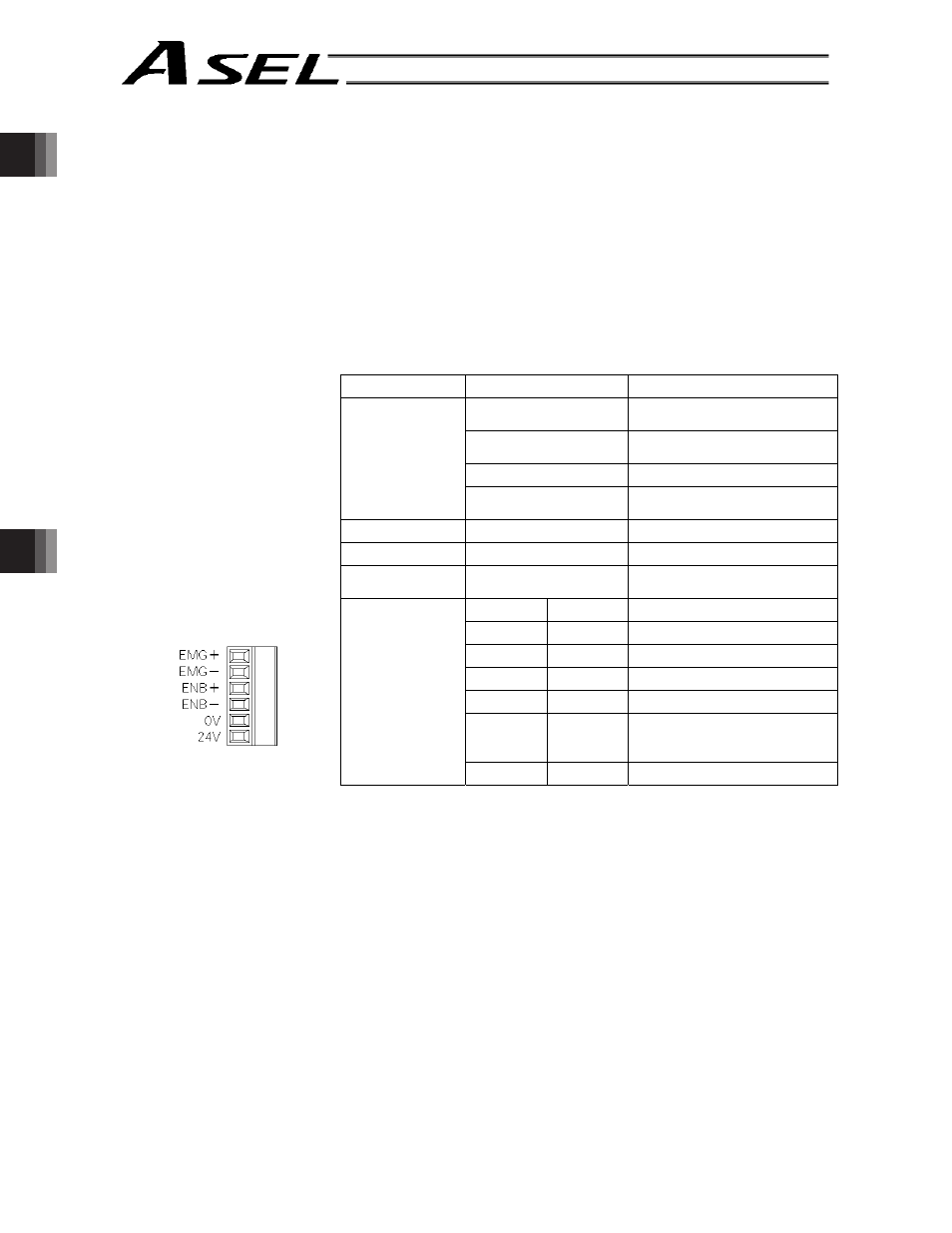
[14] Control power & system
I/O connector:
This connector is used to input the 24-VDC control power and connect the
emergency stop switch and enable switch.
The power supply connected to this connector is used for the controller
internal power, brake power, and so on, and not used as the motor drive
source.
The 0-V input is connected to the ground for the controller’s internal power
supply and is not insulated.
Item
Specification
Remarks
3.5 mm, 2-piece
COMBICON, 6 pins
MC1.5/6-G-3.5 by Phoenix
Contact
Cable-end connector
MC1.5/6-ST-3.5 by Phoenix
Contact
Applicable wire size
AWG20 ~ 16 (0.5 ~ 1.25 sq)
Applicable
connector
Recommended stripped-
wire length
7 mm
Connector name
CP EMG ENB
Input voltage
24 VDC + 10%/-10%
Maximum input
current
1.2 A
No.
Name
Function
1
EMG+
Emergency stop switch +
2
EMG-
Emergency stop switch -
3
ENB+
Enable switch +
4
ENB-
Enable switch -
5
0V
Control power input ground
(Connected to the internal
ground)
Terminal
assignments
6
24V
Control power input +24 V
[15] Regenerative resistor
connector:
This connector is used to connect a regenerative resistor when the built-in
regenerative resistor alone cannot provide enough capacity in high-
acceleration/high-load operation, etc. This connector is not normally used
with the ASEL controller.