CONTREX CX-1200 User Manual
Page 367
C - 21
(Continued)
Appendix C: Parameter Summary Numeric Quick Reference (continued)
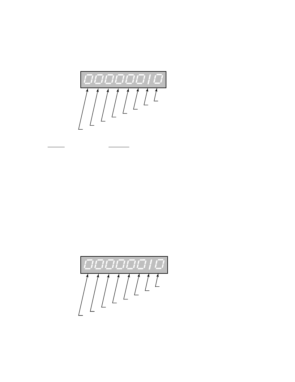
MP-121 PLC 107-100
PLC 107-100 (MP-121) displays the status of PLC bits 107-100 (See graphic and list below). A “1” in any bit indicates
that the output is “active”. The digital outputs are active low (current sinking).
Digital Output 0
Digital Output 1
Digital Output 2
Digital Output 3
Digital Output 4
Digital Output 5
Digital Output 6
Digital Output 7
Bit Name
Description
Digital Output 0
Drive Enable
Digital Output 1
Batch Done
Digital Output 2
Sync Alarm
Digital Output 3
Fwd/Rvs
Digital Output 4
Lead Sync Absent
Digital Output 5
Foll Sync Absent
Digital Output 6
Hi/Low Speed Alarm
Digital Output 7
Zero Speed
Minimum Value: 00000000
Maximum Value: 11111111
Units: Coded
MP-122 PLC 115-108
PLC 115-108 (MP-122) displays the status of the internal PLC control bits 115-108 (See graphic below). A “1” in any bit
indicates that the bit is “active”. These internal bits (control relays) can be used as global “control relays”. For
example, they can be used to create one-shots or latches. They can also be used to simplify programming.
Temporary Bit 1
Temporary Bit 2
Temporary Bit 3
Temporary Bit 4
Temporary Bit 5
Temporary Bit 6
Temporary Bit 7
Temporary Bit 8
Minimum Value: 00000000
Maximum Value: 11111111
Units: Coded