CONTREX CX-1200 User Manual
Page 271
7 - 32
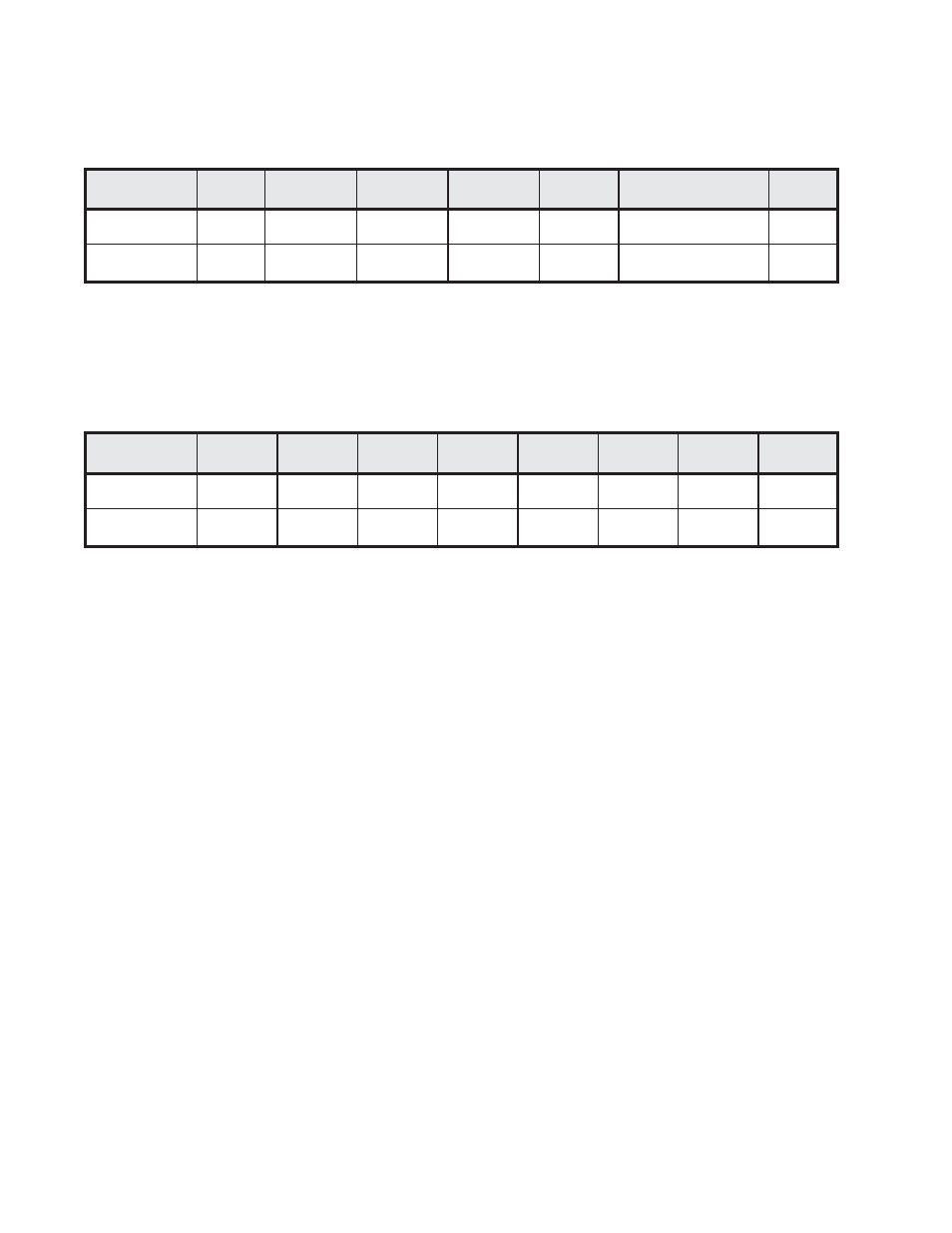
FUNCTION (13) DATA READ PARAMETER CONTROL BYTE
Table 37 CX-1200 Response
Character #
DESC
ASCII
STX
Msg Error
Separator
Parm #
Equals
Parm Control Byte
ETX
1
2
3
4
5
6-13
14
^B
0-FF
,
1-999
=
0-1
^C
Parameter Control Byte Field
This field will contain an ASCII string of 8 characters, of the range 0 to 1, representing, in binary
format, the parameter control byte for the parameter requested. If there is an error in the request, this
field will contain the error code number preceded by an “E” (e.g., “E3”).
Parameter Control Byte field per Table 37
Character #
DESC
ASCII
Bit 7
Bit 6
Bit 5
Bit 4
Bit 3
Bit 2
Bit 1
Bit 0
6
7
8
9
10
11
12
13
0-1
0-1
0-1
0-1
0-1
0-1
0-1
0-1
Parameter Control Byte Definitions:
Bit 7
=
(1) Negative Numbers are Possible (0) Positive Numbers Only
Bit 6
=
(1) Leading Zero’s OK (0) No Leading Zero’s
Bit 5
=
(1) Restricted (0) Not Restricted
Bit 4
=
(1) Parameter Define (0) Parameter is NOT Defined
Bit 3
=
Not Used (Reserved) always 0
Bit 2
=
(1) Floating Decimal Point Number (0) Fixed Decimal Point Number
Bit 1
=
(1) Binary Number (0) Decimal Number
Bit 0
=
(1) Integer (0) Non-Integer
Message Error Response Field
Consists of 2 Bytes (ASCII “HEX”)
“ASCII HEX” means the numeric value in the field is NOT represented as a decimal (Base 10) Number. The
Number is represented by the characters: 0 through 9 and A through F for the HEX equivalent of the binary
number.
Message Error Bit Definitions:
Bit 7
=
(1) CRC Failure
Bit 6
=
(1) Buffer Overflow
Bit 5
=
(1) ETX Not Received/Data Field Error
Bit 4
=
(1) Invalid Function/Data Error
Bit 3
=
(1) Over-Run Error
Bit 2
=
(1) Noise Error
Bit 1
=
(1) Framing Error
Bit 0
=
(1) Parity Error
Example:
“86” = the number 10000110 (binary) would indicate a CRC failure with Noise errors and Framing
errors occurred when the transmission message was received.