CONTREX CX-1200 User Manual
Page 187
5 - 94
After “AND 0 S0” (stack falls):
S1: 1 (S1 remains the same after the shift down)
S0: 1
R: 0
After “OR 0 S0” (stack falls):
S1: 1
S0: 1
R: 1
After “OUT 101 D0_1”:
S1: 1
S0: 1
R: 1
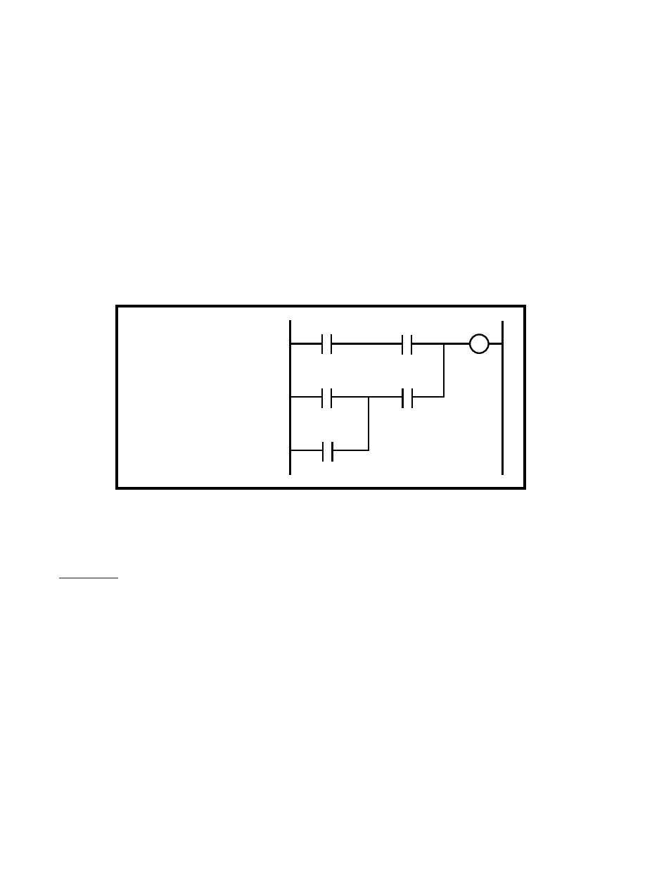
The ladder diagram can be constructed differently to simplify the programming.
DI_8
8
DI_1
101
DI_11
11
DI_9
9
DI_10
10
8
DI_8
9
DI_9
11
DI_11
12
DI_12
10
DI_10
0
S0
101
DO_1
LOAD
AND
LOAD
OR
AND
OR
OUT
DI_12
12
In fact, most rungs can be simplified to require only one additional “LOAD” (other than the opening
“LOAD”) and one operation with the “S0” register (i.e., the “S1” register would not be needed).
The Latches
There are four latches that are available with the PLC. Each has two inputs and one output. The output
reflects the state of the latch, either “1” (ON) or “0” (Off). When the set input is “1” (true), the state of the
latch (the output) will be “1” (On). When the reset input is “1” (true), then the state of the Latch will be “O”
(Off). The set and reset inputs need only be true for one scan. The latch will retain its state (while the power
is “On”) until the opposite input becomes true. If both inputs are “1” (true) at the same time, the state of the
latch will be “0” (Off).
The set inputs (act as coils) are labelled:
Lch1 Set (PLC Bit 116)
Lch2 Set (PLC Bit 117)
Lch3 Set (PLC Bit 118)
Lch4 Set (PLC Bit 119)