Alcatel Carrier Internetworking Solutions Omni Switch/Router User Manual
Page 918
Obtaining Status and Statistical Information
Page 29-46
Control Signal
This table (which displays only for serial ports, not T1 or E1 ports) lists two or more
control signals along with their current state. If a
V.35
,
RS-232
,
RS-530
, or
RS-449
cable is
attached then this table lists the following signals:
•
DTR
(Data Terminal Ready.)
•
RTS
(Request To Send.)
•
DSR
(Data Set Ready.)
•
CTS
(Clear To Send.)
•
DCD
(Data Carrier Detect.)
The
ON/OFF
indicator below the signal name tells you the current status of the signal.
Under normal operating conditions (physical connection is good and VC is administra-
tively enabled), all signals should be On.
Whether the signal is an input or an output depends on whether the
WSX
is a physical
DTE
or
DCE
. The following table shows the Input/Output status of each signal type.
If using an
X.21
cable, then the table shown in the sample display is replaced by the
following table:
Control
C(Control)
I(Indicator)
Signal
ON
ON
This
X.21
table shows 2 rather than 5 signal statuses. The
C
signal is similar to the
RTS
(Request To Send) signal. The
I
signal is similar to the
DCD
(Data Carrier Detect) signal.
Under normal operating conditions, both the
C
and
I
signals should be On.
Whether the signal is an input or an output depends on whether the
WSX
is a physical
DTE
or
DCE
. The following table shows the Input/Output status of each signal type.
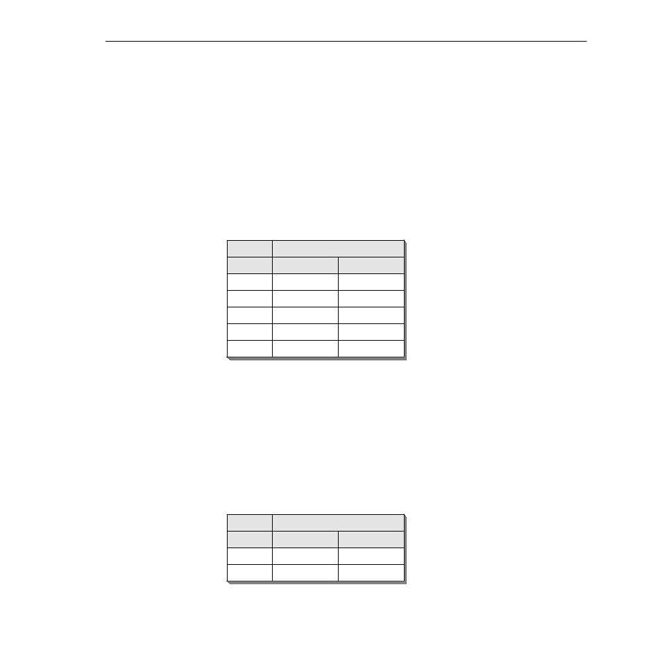
Signal Direction When Port Is...
Signal
DCE
DTE
DTR
In
Out
RTS
In
Out
DSR
Out
In
CTS
Out
In
DCD
Out
In
Signal Direction When Port Is...
Signal
DCE
DTE
C
In
Out
I
Out
In