Application example 5 – Alcatel Carrier Internetworking Solutions Omni Switch/Router User Manual
Page 721
Application Example 5
Page 24-11
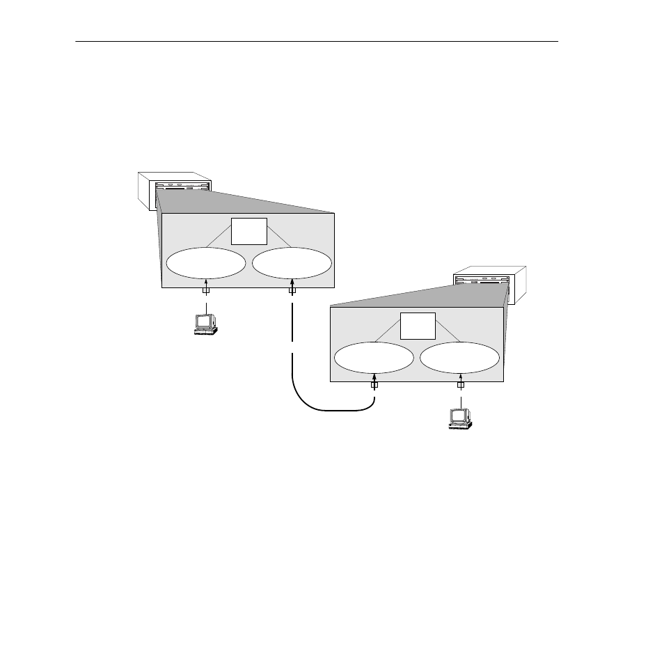
The Solution
The recommended solution is to add a port policy to
VLAN
D
, as is shown in the figure
below. A port policy can be defined in addition to any other policies defined for a
VLAN
. If
VLAN
D
has a port policy that includes port 2 on Switch 1 and port 1 on Switch 2 – the ports
to which the backbone is connected –
VLAN
D
and its internal router will activate immedi-
ately in both Switch 1 and Switch 2. Traffic (i.e., routing information) can then flow between
Switch 1 and Switch 2 over the backbone. Switch 1 will be aware of network 30 and Switch 2
will be aware of network 10.
1
2
3
4
5
6
7
8
1
2
3
4
5
6
12345678
123456
Omni Switch/Router 2
Omni Switch/Router 1
IP
Workstation
10.10.10.1
Port 1
IP
Workstation
30.30.30.1
Port 2
Port 2
Port 1
VLAN
C
IP
address 10.10.10.0
10.10.10.
2
Internal
IP
Router
20.20.20.
3
20.20.20.
4
Internal
IP
Router
30.30.30.
2
VLAN
E
IP
address 30.30.30.0
Backbone
Adding a port policy to VLAN D
that includes the ports to which the
backbone is connected solves the
problem. VLAN D now activates
immediately – since it has ports
assigned – and traffic can flow
between the two switches.
VLAN
D
IP
address 20.20.20.0
Port 2
VLAN
D
IP
address 20.20.20.0
Port 1
Please Take Note
Refer to Chapter 20, “Configuring
Group and VLAN Policies,” for infor-
mation on original and current port
policy functionality.