1 encoder connections, 1 encoder connections - 24, Encoder connections -24 – Yaskawa Sigma II Series Servo System User Manual
Page 62: Incremental encoders
Sigma II User’s Manual
Chapter 3: Wiring
3 - 24
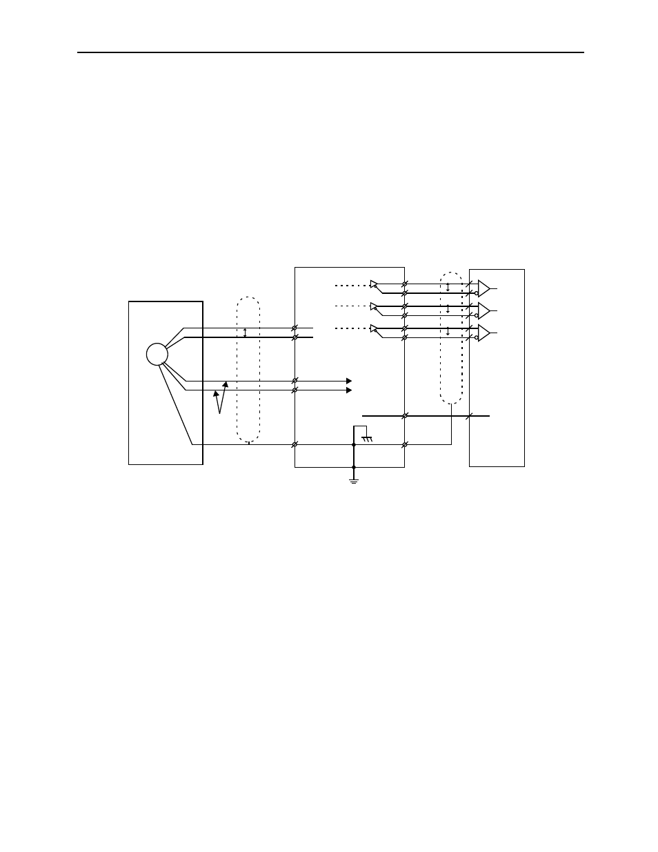
3.5 Wiring Encoders (for SGMGH and SGMSH Motors Only)
The following sections describe the procedure for wiring a servo amplifier to the encoder.
3.5.1
Encoder Connections
The following diagrams show the wiring of the encoder output from the motor to
CN2 of the servo amplifier, and PG output signals from CN1 to the controller. This
applies to both incremental and absolute encoders of SGMGH and SGMSH motors
only. The numbers in parentheses ( ) are applicable to SGMAH motors. For SGMPH
motors, refer to the Sigma II Servo System Product Catalog Supplement.
Incremental Encoders
Incremental encoder
Servo amplifier
Applicable line
Output line-driver
receiver
SN75175
manufactured
by T/I, or the
equivalent
A phase
B phase
C phase
CN2
PAO
CN1
SN751LS194 manufactured
by T/I, or the equivalent
C (5)
D (6)
H (1)
G (2)
J
PG
2-5
2-6
2-1
2-2
PG5V
PG0V
P
1-33
1-34
1-35
1-36
1-19
1-20
/PAO
PBO
/PBO
PCO
/PCO
22AWG
0V
0V
1-1
SG
P
P
P
(Shell)
Connector
Connector shell
shell
Shield wires
- Tag Generator (30 pages)
- MP3300iec (82 pages)
- 1000 Hz High Frequency (18 pages)
- 1000 Series (7 pages)
- PS-A10LB (39 pages)
- iQpump Micro User Manual (300 pages)
- 1000 Series Drive Option - Digital Input (30 pages)
- 1000 Series Drive Option - CANopen (39 pages)
- 1000 Series Drive Option - Analog Monitor (27 pages)
- 1000 Series Drive Option - CANopen Technical Manual (37 pages)
- 1000 Series Drive Option - CC-Link (38 pages)
- 1000 Series Drive Option - CC-Link Technical Manual (36 pages)
- 1000 Series Drive Option - DeviceNet (37 pages)
- 1000 Series Drive Option - DeviceNet Technical Manual (81 pages)
- 1000 Series Drive Option - MECHATROLINK-II (32 pages)
- 1000 Series Drive Option - Digital Output (31 pages)
- 1000 Series Drive Option - MECHATROLINK-II Technical Manual (41 pages)
- 1000 Series Drive Option - Profibus-DP (35 pages)
- AC Drive 1000-Series Option PG-RT3 Motor (36 pages)
- Z1000U HVAC MATRIX Drive Quick Start (378 pages)
- 1000 Series Operator Mounting Kit NEMA Type 4X (20 pages)
- 1000 Series Drive Option - Profibus-DP Technical Manual (44 pages)
- CopyUnitManager (38 pages)
- 1000 Series Option - JVOP-182 Remote LED (58 pages)
- 1000 Series Option - PG-X3 Line Driver (31 pages)
- SI-EN3 Technical Manual (68 pages)
- JVOP-181 USB Copy Unit (2 pages)
- JVOP-181 (22 pages)
- SI-EN3 (54 pages)
- MECHATROLINK-III (35 pages)
- SI-ET3 (49 pages)
- EtherNet/IP (50 pages)
- SI-EM3 (51 pages)
- 1000-Series Option PG-E3 Motor Encoder Feedback (33 pages)
- 1000-Series Option SI-EP3 PROFINET (56 pages)
- PROFINET (62 pages)
- AC Drive 1000-Series Option PG-RT3 Motor (45 pages)
- SI-EP3 PROFINET Technical Manual (53 pages)
- A1000 Drive Option - BACnet MS/TP (48 pages)
- 120 Series I/O Modules (308 pages)
- A1000 12-Pulse (92 pages)
- A1000 Drive Software Technical Manual (16 pages)
- A1000 Quick Start (2 pages)
- JUNMA Series AC SERVOMOTOR (1 page)
- A1000 Option DI-101 120 Vac Digital Input Option (24 pages)