3 using the encoder signal output, 3 using the encoder signal output - 22, Using the encoder signal output -22 – Yaskawa Sigma II Series Servo System User Manual
Page 108
Sigma II User’s Manual
Chapter 5: Parameter Settings and Functions
5 - 22
5.2.3
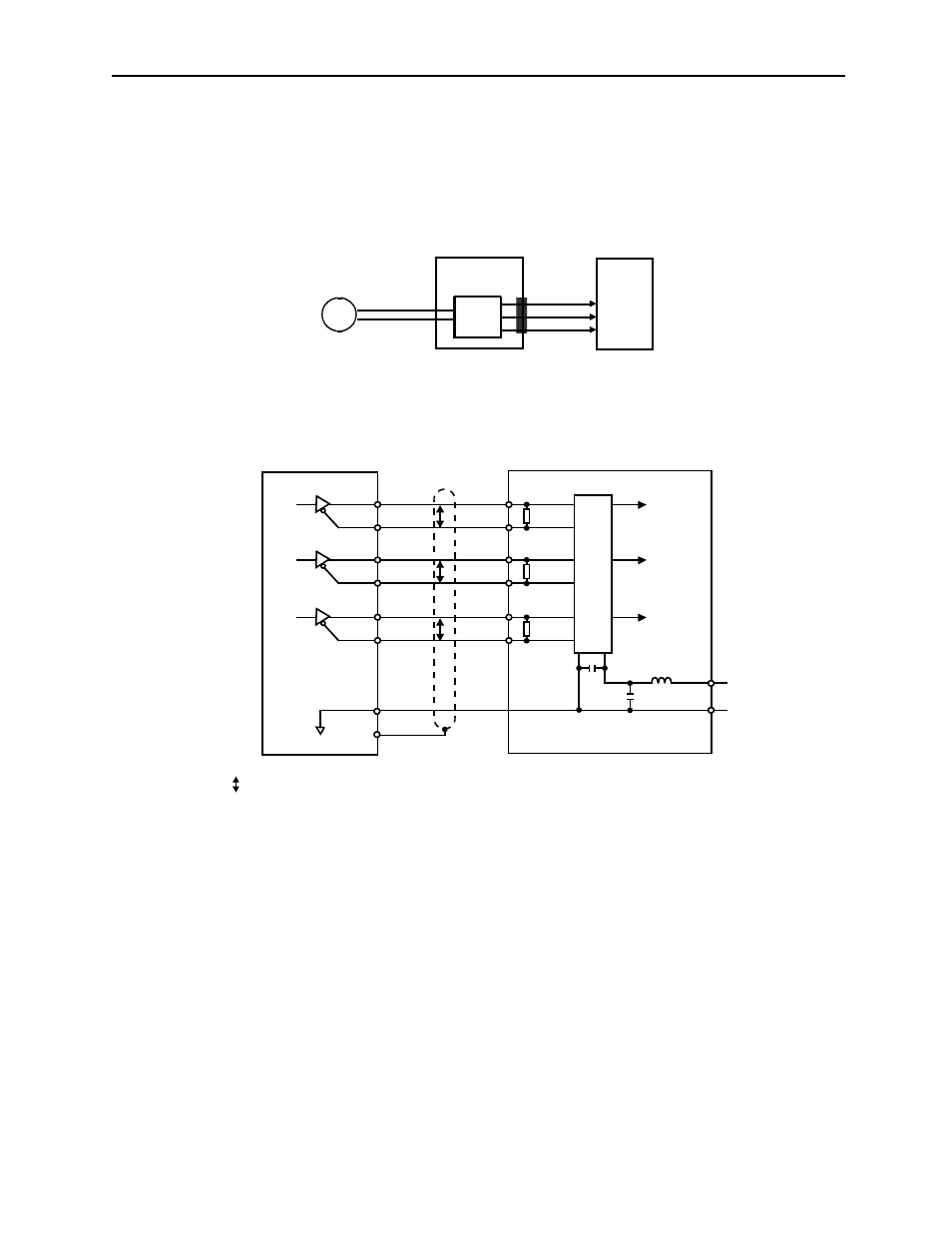
Using the Encoder Signal Output
Encoder output signals divided inside the servo amplifier can be output externally.
These signals can be used to form a position control loop in the host controller.
The output circuit is for line-driver output. Connect each signal line according to the
following circuit diagram.
Note: Dividing means converting an input pulse train from the encoder mounted on the servomotor
according to the preset pulse density and outputting the converted pulse. The units are pulses per
revolution (PPR).
PG
Servo amplifier
CN2
CN1
(Servomotor)
Encoder
Host controller
Phase A
Phase B
Phase C
Serial data
/PBO
R = 220 to 470
Ω
C = 0.1
μF (Decoupling capacitor)
PBO
P
P
P represents twisted pair wires.
P
/PCO
PCO
/PAO
PAO
Phase A
Phase B
Phase C
CN1-33
CN1-34
CN1-35
CN1-36
CN1-19
CN1-20
CN1-1
Phase A
Phase B
Phase C
0V
Choke coil
Smoothing
capacitor
16
0V
+5V
8
9
10
7
C
+
-
+5V
11
0V
6
5
3
2
1
R
R
R
Servo amplifier
Host controller
Line receiver
Shield
Connector shell
- Tag Generator (30 pages)
- MP3300iec (82 pages)
- 1000 Hz High Frequency (18 pages)
- 1000 Series (7 pages)
- PS-A10LB (39 pages)
- iQpump Micro User Manual (300 pages)
- 1000 Series Drive Option - Digital Input (30 pages)
- 1000 Series Drive Option - CANopen (39 pages)
- 1000 Series Drive Option - Analog Monitor (27 pages)
- 1000 Series Drive Option - CANopen Technical Manual (37 pages)
- 1000 Series Drive Option - CC-Link (38 pages)
- 1000 Series Drive Option - CC-Link Technical Manual (36 pages)
- 1000 Series Drive Option - DeviceNet (37 pages)
- 1000 Series Drive Option - DeviceNet Technical Manual (81 pages)
- 1000 Series Drive Option - MECHATROLINK-II (32 pages)
- 1000 Series Drive Option - Digital Output (31 pages)
- 1000 Series Drive Option - MECHATROLINK-II Technical Manual (41 pages)
- 1000 Series Drive Option - Profibus-DP (35 pages)
- AC Drive 1000-Series Option PG-RT3 Motor (36 pages)
- Z1000U HVAC MATRIX Drive Quick Start (378 pages)
- 1000 Series Operator Mounting Kit NEMA Type 4X (20 pages)
- 1000 Series Drive Option - Profibus-DP Technical Manual (44 pages)
- CopyUnitManager (38 pages)
- 1000 Series Option - JVOP-182 Remote LED (58 pages)
- 1000 Series Option - PG-X3 Line Driver (31 pages)
- SI-EN3 Technical Manual (68 pages)
- JVOP-181 (22 pages)
- JVOP-181 USB Copy Unit (2 pages)
- SI-EN3 (54 pages)
- SI-ET3 (49 pages)
- MECHATROLINK-III (35 pages)
- EtherNet/IP (50 pages)
- SI-EM3 (51 pages)
- 1000-Series Option PG-E3 Motor Encoder Feedback (33 pages)
- 1000-Series Option SI-EP3 PROFINET (56 pages)
- PROFINET (62 pages)
- AC Drive 1000-Series Option PG-RT3 Motor (45 pages)
- SI-EP3 PROFINET Technical Manual (53 pages)
- A1000 Drive Option - BACnet MS/TP (48 pages)
- 120 Series I/O Modules (308 pages)
- A1000 12-Pulse (92 pages)
- A1000 Drive Software Technical Manual (16 pages)
- A1000 Quick Start (2 pages)
- JUNMA Series AC SERVOMOTOR (1 page)
- A1000 Option DI-101 120 Vac Digital Input Option (24 pages)