Yaskawa Sigma II Series Servo System User Manual
Page 435
Sigma II User’s Manual
Appendix A: Host Controller Connection Examples
A - 3
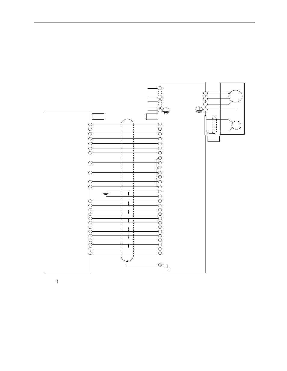
A.2 Connecting the CP-9200SH Servo Controller Module (SVA)
The following diagram shows an example of connecting to the CP-9200SH servo
controller Module (SVA). In this example, the servo amplifier is used in Speed Control
Mode.
* P indicates twistedpair wires.
CN1
+24V
+24VIN
17
47
DO0
SON
22
40
DO1
PCON
47
41
DO2
NOT
23
43
DO3
POT
48
42
DO4
ALMRST
24
44
DI2
TGON+
19
27
TGON-
28
DI1
VCMP+
43
25
VCMP-
26
DI0
SRDY+
18
29
SRDT-
30
DI3
ALM+
44
31
024V
ALM-
45
32
21
BAT (+)
BAT (-)
22
SENS
SEN
SENSG
SG
26
2
CN
4
1
TLIMPG
PA
TLIMP
0V
INA
PG0V
PCL
PC
PBL
PB
PAL
9
15
14
13
12
11
10
8
7
4
3
SG
PCO
PBO
TREF
SG
VREF
SG
PAO
19
36
35
34
33
10
9
6
5
20
1
Connector shell
*
Yaskawa's
CP9200SH SVA
M
PG
W
V
U
CN2
Servomotor
A (1)
B (2)
C (3)
D (4)
Servopack
SGDM
L1C
L3
L2
L1
L2C
P
P
P
P
P
P
P
*PCO
*PBO
*PAO
P Indicates twisted pair wires.
- Tag Generator (30 pages)
- MP3300iec (82 pages)
- 1000 Hz High Frequency (18 pages)
- 1000 Series (7 pages)
- PS-A10LB (39 pages)
- iQpump Micro User Manual (300 pages)
- 1000 Series Drive Option - Digital Input (30 pages)
- 1000 Series Drive Option - CANopen (39 pages)
- 1000 Series Drive Option - Analog Monitor (27 pages)
- 1000 Series Drive Option - CANopen Technical Manual (37 pages)
- 1000 Series Drive Option - CC-Link (38 pages)
- 1000 Series Drive Option - CC-Link Technical Manual (36 pages)
- 1000 Series Drive Option - DeviceNet (37 pages)
- 1000 Series Drive Option - DeviceNet Technical Manual (81 pages)
- 1000 Series Drive Option - MECHATROLINK-II (32 pages)
- 1000 Series Drive Option - Digital Output (31 pages)
- 1000 Series Drive Option - MECHATROLINK-II Technical Manual (41 pages)
- 1000 Series Drive Option - Profibus-DP (35 pages)
- AC Drive 1000-Series Option PG-RT3 Motor (36 pages)
- Z1000U HVAC MATRIX Drive Quick Start (378 pages)
- 1000 Series Operator Mounting Kit NEMA Type 4X (20 pages)
- 1000 Series Drive Option - Profibus-DP Technical Manual (44 pages)
- CopyUnitManager (38 pages)
- 1000 Series Option - JVOP-182 Remote LED (58 pages)
- 1000 Series Option - PG-X3 Line Driver (31 pages)
- SI-EN3 Technical Manual (68 pages)
- JVOP-181 (22 pages)
- JVOP-181 USB Copy Unit (2 pages)
- SI-EN3 (54 pages)
- SI-ET3 (49 pages)
- MECHATROLINK-III (35 pages)
- EtherNet/IP (50 pages)
- SI-EM3 (51 pages)
- 1000-Series Option PG-E3 Motor Encoder Feedback (33 pages)
- 1000-Series Option SI-EP3 PROFINET (56 pages)
- PROFINET (62 pages)
- AC Drive 1000-Series Option PG-RT3 Motor (45 pages)
- SI-EP3 PROFINET Technical Manual (53 pages)
- A1000 Drive Option - BACnet MS/TP (48 pages)
- 120 Series I/O Modules (308 pages)
- A1000 12-Pulse (92 pages)
- A1000 Drive Software Technical Manual (16 pages)
- A1000 Quick Start (2 pages)
- JUNMA Series AC SERVOMOTOR (1 page)
- A1000 Option DI-101 120 Vac Digital Input Option (24 pages)