Connection example 1: line-driver output, Connection example 2: open-collector output – Yaskawa Sigma II Series Servo System User Manual
Page 103
Sigma II User’s Manual
Chapter 5: Parameter Settings and Functions
5 - 17
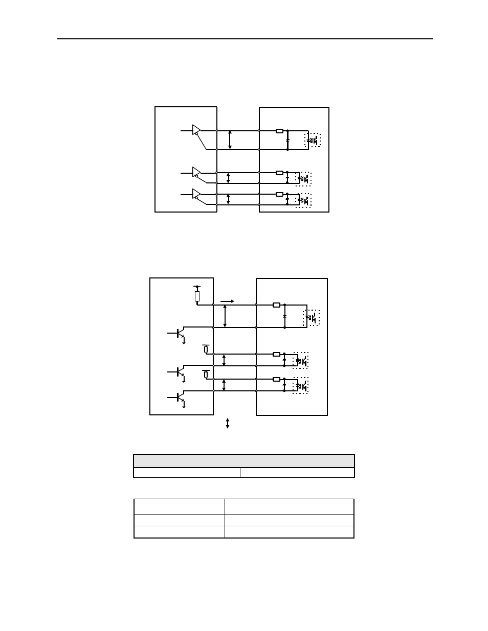
Connection Example 1: Line-driver Output
Applicable line driver: SN75174 manufactured by Texas Instruments Inc., MC3487
or equivalent
Connection Example 2: Open-collector Output
Set limiting resistor R1 so that input current, I, falls within the following range:
The examples below show how to select the pull-up resistor R1 so the input current,
I, falls between 7 and 15mA.
Note: The following table shows the signal logic for an open-collector output.
This circuit uses the 12V power supply built into the servo amplifier. The input is
not isolated in this case.
Application Examples of V = IR
R1 = 1k
Ω with V
CC
= 12V ±5%
R1 = 180
Ω with V
CC
= 5V ±5%
Tr1 Output Level
Signal Logic
ON
Equivalent to high-level input
OFF
Equivalent to low-level input
Photocoupler
Line-driver
P
Servo amplifier
P
P
Host controller
PULS
/PULS
SIGN
/SIGN
CLR
/CLR
CN1-7
CN1-8
CN1-11
CN1-12
CN1-15
CN1-14
150
Ω
P represents twisted pair wires
Vcc
P
Servo amplifier
Photocoupler
Host controller
R1
i
Tr1
P
R1
P
R1
PULS
/PULS
SIGN
/SIGN
CLR
/CLR
CN1-7
CN1-8
CN1-11
CN1-12
CN1-15
CN1-14
150
Ω