4) 17 bit incremental/absolute encoder, 5ed ?al1, C data + m – Yaskawa Sigma II Series Servo System User Manual
Page 357: D data − n
Sigma II User’s Manual
Chapter 8: Ratings and Characteristics
8 - 27
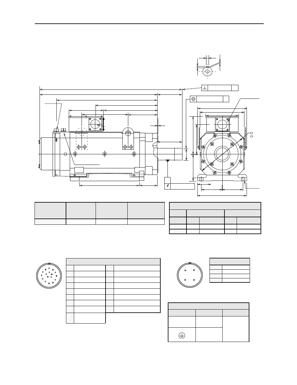
(4) 17 Bit Incremental/Absolute Encoder
Fan connector
Power wiring
38.19 (970)
31.50 (800)
26.93 (684)
16.57 (421)
12.32 (313)
7.87 (200)
14.41 (366)
9.29 (236)
6.69 (170)
12.99 (330)
11.81 (300)
8.66 (220)
5.49 (139.5)
3.54 (90)
15.98 (406)
4.75 (121)
4-
Φ0.94
12.99 (330)
5.49 (139.5)
(
Φ24)
6.69 (170)
Φ
3.
1
5
(Φ
80
)
7.
09
(18
0
)
10
.2
4
(2
60
)
7
.91
(2
01
)
0.0020 (0.05)
A
Φ0.0020 (Φ0.05) A
A
0.0012 (0.03)
0.87 (22) = W
0.55
(14) = T
0.35 (9)
Y
Y
Cross-section Y-Y
0.20 (5)
Encoder connector
Φ2.40 (Φ61)
Ι
13.8
Ι
350
(
)
Approximate
Mass
lb (kg)
Allowable Radial
Load
lb (N)
Allowable Thrust Load
lb (N)
5ED
?AL1
772 (350)
1895 (8428)
485 (2156)
Note:
1.
Dimensions are the same when using either incremental or absolute
encoders.
2.
Tolerances on the dimensions of flange type LB, of shaft extensions S,
and of keyway width and depth are based on JIS (Japanese Industrial
Standard)
B0401 “Limits and Fits for Engineering.”
Specified Tolerances
Dimension
*T
*W
Unit
Length
Tolerance
Length
Tolerance
in
0.55
+0.0000 -0.00433
0.87
+0.0000 -0.00204
mm
14
+0.000 -0.110
22
+0.000 -0.052
A
B
C
D
M
N P
T
E
K
G
F
J
S
R
L
H
Encoder Plug
Fan Connector
A
B
D
C
Power Wiring Terminal Box
Terminal
Connection
Screw Size
U, V, W
Motor
M10
Ground
Receptacle: CE05-2A18-10PD-B
Non-environmental mating connector:
MS3108B18-10S (L-Type)
Fan Connector
A
U Phase
B
V Phase
C
W Phase
D
—
Connector Wiring on the Encoders
A
—
K
—
B
—
L
—
C Data +
M
—
D Data
−
N
—
E
—
P
—
F
—
R
—
G 0V
S Battery
− (Note*)
H +5V
dc
T
Battery + (Note*)
J
FG (Frame
Ground)
*Note: Used with an absolute
encoder only.