Yaskawa Sigma II Series Servo System User Manual
Page 472
Sigma II User’s Manual
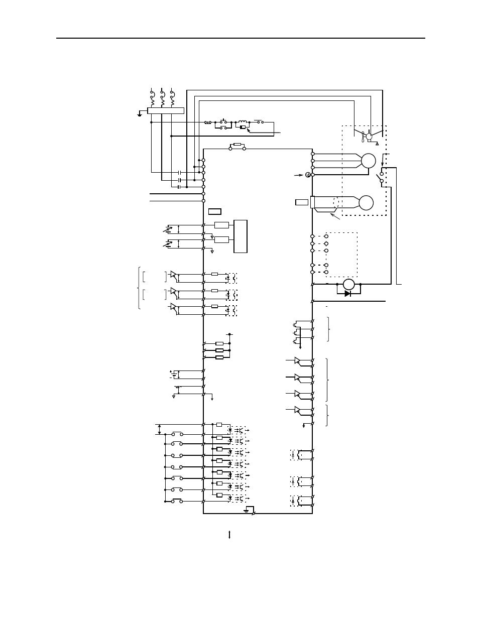
Appendix C: Examples of Standard Connections
C - 6
400V (37kW to 55kW)
Photocoupler maximum output:
Operating voltage: 30V
DC
Operating current: 50mA
DC
Reference speed:
±2V to ±10V/rated speed (set by parameter)
Torque reference:
1 to ±10V/rated torque (set by parameter)
Alarm code maximum output:
Operating voltage: 30V
DC
Operating current: 20mA
DC
P: Indicates twisted wire pairs.
1CN
PG
M
Noise filter
SGDH Servo Amplifier
Three-phase 380 to 480V
ac
(50/60Hz)
R
S
T
1MCCB
Power Power
1MC
1MC
1MC
SUP
Be sure to attach a
B1
B2
L1/R
L2/S
U
V
DC24P
DC24N
L3/T
W
PULS
/PULS
PULS
P
SIGN
CLR
7
/SIGN
P
P
/CLR
8
11
12
15
14
150W
38
39
33
34
35
36
19
20
49
1
48
37
25
26
27
28
29
30
31
Used only with
an absolute encoder
Servo ON
Proportional (P) control
Forward run
Reverse run
Alarm reset
Forward current
/V-CMP+
/T-GON+
/S-RDY+
/S-RDY-
/T-GON-
/V-CMP-
Reverse current
prohibited
prohibited
limit ON
limit ON
ALO1
ALO3
ALO3
PAO
/PAO
PBO
/PBO
PCO
/PCO
PSO
/PSO
SG
Amount of S-phase rotation
PG dividing ratio output
Be sure to properly
Optical
prepare the end of
Servomotor
encoder
Applicable line receiver
SN75175 or MC3486 manufac-
tured by T/I, or the equivalent
Serial data output
Applicable line receiver
SN75175 or MC3486 manufac-
tured by T/I, or the equivalent
Positioning completed
(ON when positioning is
completed)
T-GON output
Servo ready output
(ON at levels above the setting)
(ON when ready)
Connect shield to connector shell
Connector shell
Position reference
CW
CLR
Phase A
A (1)
B (2)
C (3)
D (4)
Be sure to
ground
OFF
ON
1Ry
ALM
+
FG
(/COIN+)
(/COIN-)
Speed coincidence detection
(ON when speed coincides)
Fan
U(A) V(B) W(C)
Regenerative Resistor
the shielded wire.
1
1B
+24V
1Ry
1D
0V
ALM
-
32
0V
+10
-15 %
DU
DW
DV
DBON
DB24
Dynamic
Brake
*The time constant for the primary filter is 47
μs
2CN
SIGN
CCW
Phase B
surge suppressor to
the excitation coil of
the magnetic contactor
and relay.
P
LPF*
P
LPF*
V-REF
9
10
5
6
SG
T-REF
SG
A/D
24V
DC
+10% maximum
PL1
PL2
3
13
18
PL3
+12V
Open-collector
reference
power supply
Backup battery 2.8 to 4.5V
(When using an absolute encoder).
SEN signal input
(When using an absolute encoder).
21
BAT (+)
P
SEN
SG
22
4
2
47
40
41
42
43
44
45
46
P
BAT (-)
+24V
+5V
0V
+24V
/S-ON
/P-CON
P-OT
N-OT
ALM-RST
/P-CL
/N-CL
Forward run prohibited with
Reverse run prohibited with
Alarm reset with 3Ry ON
P control with 2Ry ON
Reverse current limit ON with 7Ry ON
Forward current limit ON with 6Ry ON
N-LS OPEN
P-LS OPEN
Servo ON with 1Ry ON
24V
DC
±15%
1Ry
2RY
P-LS
N-LS
3Ry
6Ry
7RY
4.7k
Ω
380 ~ 480V
OV
Note:The thermal protector must be wired
to provide protection in the event of
the motor overheating.
**Thermal
Protector