2 high-speed positioning, 1 setting servo gain, 2 high-speed positioning - 10 – Yaskawa Sigma II Series Servo System User Manual
Page 242: 1 setting servo gain - 10, 2 high-speed positioning -10, Setting servo gain -10, Setting speed loop gain
Sigma II User’s Manual
Chapter 6: Servo Adjustment
6 - 10
6.2 High-Speed Positioning
This section provides technical information on high-speed positioning.
6.2.1
Setting Servo Gain
Use the servo gain setting function in the following cases.
•
To check each servo gain value that is automatically set after auto-tuning.
•
To directly set each of the above servo gain values in another servo amplifier.
•
To further refine responsiveness after auto-tuning (either to increase responsive-
ness or to reduce it).
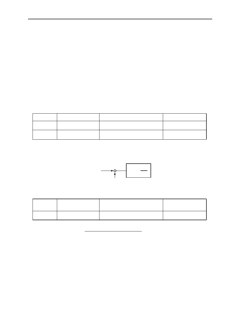
Setting Speed Loop Gain
Set the following speed loop related parameters as required.
The higher the speed loop gain, or the smaller the speed loop integral time constant
value, the faster the speed control response will be. There is, however, a certain
limit depending on machine characteristics.
Speed loop gain K
v
is adjusted in 1Hz increments provided that the following
parameter is set correctly.
The load inertia of the servo amplifier reflected at the motor shaft is default set to the
rotor inertia of the servomotor. Therefore, obtain the inertia ratio from the above
formula and set parameter Pn103 properly.
The above parameters are automatically set by the auto-tuning operation.
Parameter
Signal
Setting
Application
Pn100
Speed Loop Gain (K
v
)
Setting Range: 1 to 2000Hz
Default Setting: 40Hz
Speed Control, Position
Control
Pn101
Speed Loop Integral
Time Constant (T
i
)
Setting Range: 15 to 51200 × 0.01ms
Default Setting: 2000 × 0.01ms
Speed Control, Position
Control
Parameter
Signal
Setting
(%)
Application
Pn103
Inertia Ratio
Setting Range: 0 to 10000
Default Setting: 0
Speed/Torque Control,
Position Control
K
V
(
1+
)
1
TiS
loop gain
Speed feedback
Speed reference +
-
Inertia Ratio =
× 100%
Motor load inertia (J
L
)
Servomotor rotor inertia (J
M
)