6 selecting a regenerative resistor, 6 selecting a regenerative resistor - 84, 6 selecting a regenerative resistor -84 – Yaskawa Sigma II Series Servo System User Manual
Page 170
Sigma II User’s Manual
Chapter 5: Parameter Settings and Functions
5-84
Parameter Settings and Functions
5.6 Selecting a Regenerative Resistor
When the servomotor operates in generator mode, power is returned to the servo amplifier
side. This is called regenerative power. The regenerative power is absorbed by charging
the smoothing capacitor, but when the capacitor’s charging limit is exceeded, the
regenerative power is then reduced by the regenerative resistor.
The servomotor is driven in regeneration (generator) mode in the following conditions:
•
While decelerating to a stop during acceleration/deceleration operation.
•
With a load on the vertical axis.
•
During continuous operation with the servomotor driven from the load side (negative
load).
The capacity of the servo amplifier’s built-in regenerative resistor is designed for
short-term operation only, such as the deceleration stop period. Operation under a
negative load is not possible.
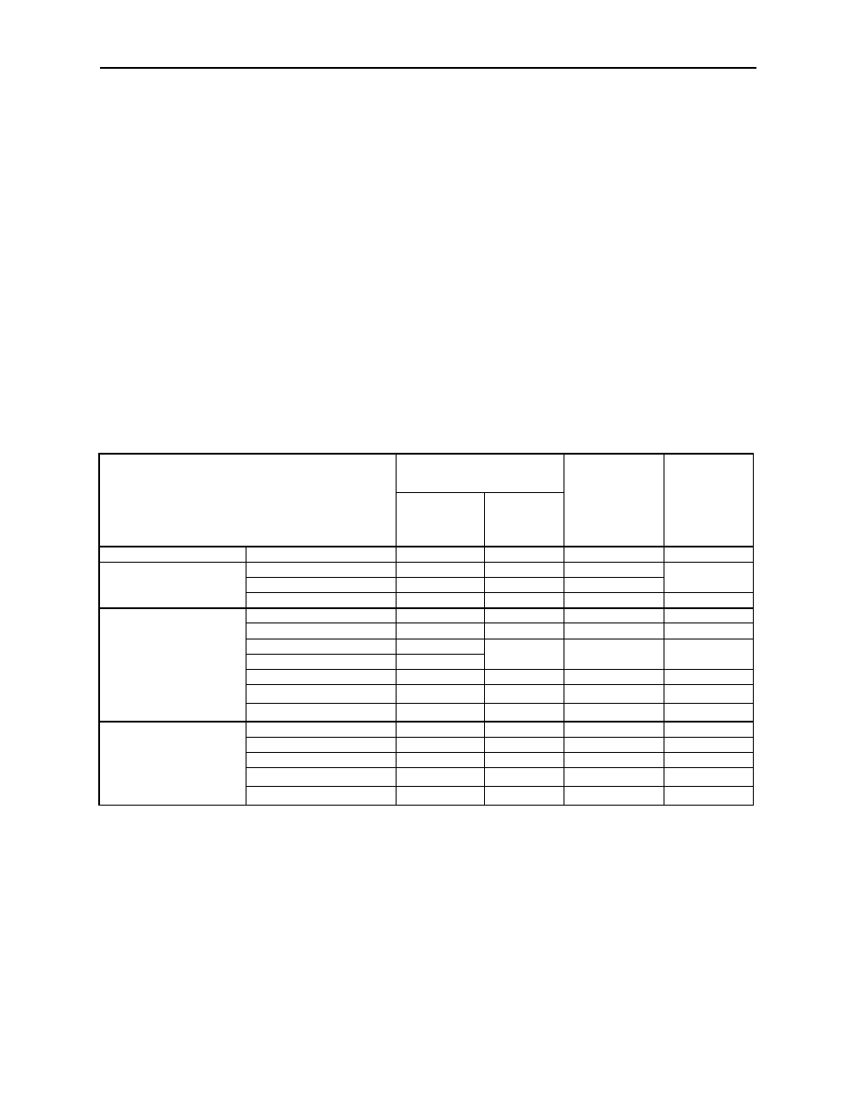
If the regenerative power exceeds the processing capacity of the servo amplifier, install an
external regenerative resistor. The following table shows the specifications of the servo
amplifier’s built-in resistor and the amount of regenerative power (average values) that it
can process.
*1
The amount of regenerative power (average value) that can be processed is rated at 20% of the
capacity of the servo amplifier’s built-in regenerative resistor.
*2
The values in parentheses are for the optional JUSP-RA04 Regenerative Resistor Unit.
*3
The values in parentheses are for the optional JUSP-RA05 Regenerative Resistor Unit.
*4
The values in parentheses are for the optional JUSP-RA18 Regenerative Resistor Unit.
*5
The values in parentheses are for the optional JUSP-RA19 Regenerative Resistor Unit.
When installing an external regenerative resistor, make sure that its resistance is
equivalent to that of the servo amplifier’s built-in resistor. If combining multiple small-
capacity regenerative resistors to increase the regenerative resistor capacity (W), select
resistors so that the resistance value, including error, equals or exceeds the minimum
allowable resistance shown in the above table.
Applicable Servo Amplifiers
Built-in Resistor
Specifications
Regenerative
Power
Processed by
Built-in
Resistor
*1
(W)
Minimum
Allowable
Resistance
(
Ω)
Resistance
(
Ω)
Capacity
(W)
Single-phase, 100V
SGDH-A3BE to -02BE
—
—
—
40
Single-phase
200V
SGDH-A3AE to -04AE
—
—
—
40
SGDH-08AE-S
50
60
12
SGDH-15AE-S
25
140
28
20
Three-phase
200V
SGDH-05AE to -10AE
50
60
12
40
SGDH-15AE
30
70
14
20
SGDH-20AE
25
140
28
12
SGDH-30AE
12.5
SGDH-50AE
8
280
56
8
SGDH-60AE
(6.25)
*2
(880)
*2
(180)
*2
5.8
SGDH-75AE to -1EAE
(3.13)
3)
(1760)
3)
(350)
3)
2.9
Three-phase
400V
SGDH-05DE to -15DE
108
70
14
73
SGDH-20DE to -30DE
45
140
28
44
SGDH-50DE
32
180
36
28
SGDH-60DE to -75DE
(18)
4)
(880)
4)
(180)
4)
18
SGDH-1ADE to -1EDE
(14.25)
5)
(1760)
5)
(350)
5)
14.2