Example of an input circuit, Speed reference inputs, Using the /p-con signal – Yaskawa Sigma II Series Servo System User Manual
Page 127
Sigma II User’s Manual
Chapter 5: Parameter Settings and Functions
5 - 41
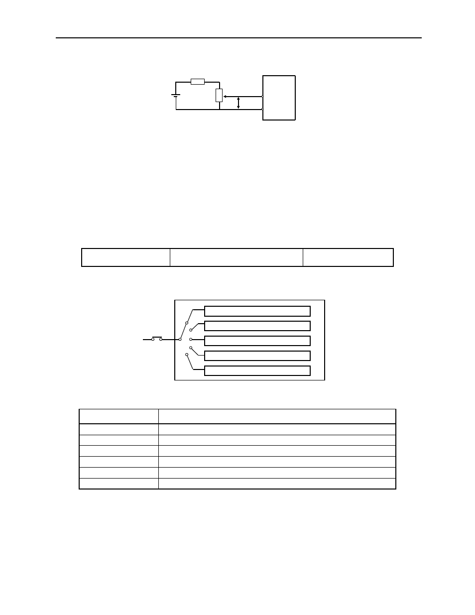
Example of an Input Circuit
Note:
•
Always use twisted pair cables for noise control.
•
del 25HP-10B
manufactured by
Speed Reference Inputs
Refer to Section 5.2.1.
Using the /P-CON Signal
The function of the input signal /P-CON varies with the setting applied to Pn000.1.
Note: The /P-CON signal function switches automatically when Pn50A.0 is set to 0.
Input /P-CON CN1-41
Proportional Control Reference, etc.
Speed/Torque Control,
Position Control
Pn000.1 Setting
/P-CON Function
0, 1
Switches between P (proportional) and PI (proportional-integral) control.
2
Not used.
3, 4, 5, 6
Switches the direction of rotation in Contact Input Speed Control Mode.
7, 8, 9
Switches the control mode.
A
Turns ON/OFF zero clamp.
B
Turns inhibit ON/OFF.
P
SG
T-REF
+12V
Servo Amplifier
CN1-9
CN1-10
1/2W minimum
470
Ω
2k
Ω
Servo Amplifier
(Pn000.1)
P and PI control switching
Zero clamp ON/OFF switching
Inhibit ON/OFF switching
Control mode switching
Direction of rotation switching
P-CON
/
- Tag Generator (30 pages)
- MP3300iec (82 pages)
- 1000 Hz High Frequency (18 pages)
- 1000 Series (7 pages)
- PS-A10LB (39 pages)
- iQpump Micro User Manual (300 pages)
- 1000 Series Drive Option - Digital Input (30 pages)
- 1000 Series Drive Option - CANopen (39 pages)
- 1000 Series Drive Option - Analog Monitor (27 pages)
- 1000 Series Drive Option - CANopen Technical Manual (37 pages)
- 1000 Series Drive Option - CC-Link (38 pages)
- 1000 Series Drive Option - CC-Link Technical Manual (36 pages)
- 1000 Series Drive Option - DeviceNet (37 pages)
- 1000 Series Drive Option - DeviceNet Technical Manual (81 pages)
- 1000 Series Drive Option - MECHATROLINK-II (32 pages)
- 1000 Series Drive Option - Digital Output (31 pages)
- 1000 Series Drive Option - MECHATROLINK-II Technical Manual (41 pages)
- 1000 Series Drive Option - Profibus-DP (35 pages)
- AC Drive 1000-Series Option PG-RT3 Motor (36 pages)
- Z1000U HVAC MATRIX Drive Quick Start (378 pages)
- 1000 Series Operator Mounting Kit NEMA Type 4X (20 pages)
- 1000 Series Drive Option - Profibus-DP Technical Manual (44 pages)
- CopyUnitManager (38 pages)
- 1000 Series Option - JVOP-182 Remote LED (58 pages)
- 1000 Series Option - PG-X3 Line Driver (31 pages)
- SI-EN3 Technical Manual (68 pages)
- JVOP-181 (22 pages)
- JVOP-181 USB Copy Unit (2 pages)
- SI-EN3 (54 pages)
- SI-ET3 (49 pages)
- MECHATROLINK-III (35 pages)
- EtherNet/IP (50 pages)
- SI-EM3 (51 pages)
- 1000-Series Option PG-E3 Motor Encoder Feedback (33 pages)
- 1000-Series Option SI-EP3 PROFINET (56 pages)
- PROFINET (62 pages)
- AC Drive 1000-Series Option PG-RT3 Motor (45 pages)
- SI-EP3 PROFINET Technical Manual (53 pages)
- A1000 Drive Option - BACnet MS/TP (48 pages)
- 120 Series I/O Modules (308 pages)
- A1000 12-Pulse (92 pages)
- A1000 Drive Software Technical Manual (16 pages)
- A1000 Quick Start (2 pages)
- JUNMA Series AC SERVOMOTOR (1 page)
- A1000 Option DI-101 120 Vac Digital Input Option (24 pages)