Absolute encoder transmission sequence – Yaskawa Sigma II Series Servo System User Manual
Page 192
Sigma II User’s Manual
Chapter 5: Parameter Settings and Functions
5-106
The final absolute data P
M
can be found by using the following formulas:
Where: P
E
= The current value read by the encoder.
M = The multi-turn data (rotation count data).
P
O
= The number of initial incremental pulses.
P
S
= The number of initial incremental pulses read at setup.
(This is saved and controlled by the host controller).
P
M
= The current value required for the user’s system.
R = The number of pulses per encoder revolution.
(Pulse count after dividing by the value of Pn201)
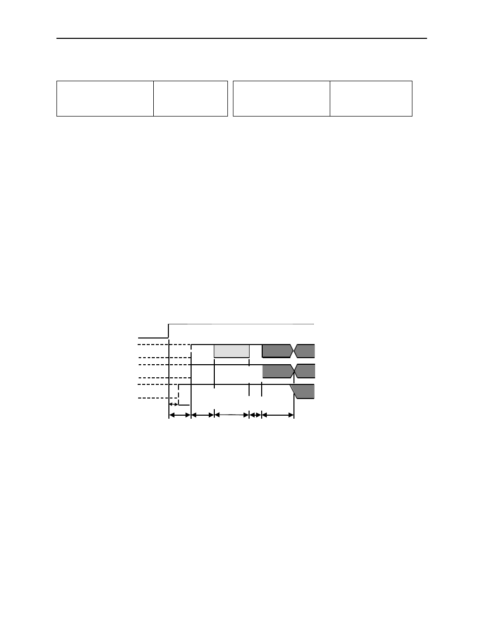
Absolute Encoder Transmission Sequence
1. Set the SEN signal at high level.
2. After 100ms, set the system to serial data reception-waiting-state. Clear the
incremental pulse up/down counter to zero.
3. Receive eight bytes of serial data.
4. The system enters a normal incremental operation state approximately 50ms
after the last serial data is received.
P
E
= M
× R + P
O
P
M
= P
E
− P
S
Forward rotation mode:
P
E
=
− M × R + P
O
P
M
= P
E
− R
S
Reverse rotation mode:
(Pn0000.0 = 1)
(
)
(Pn 000.0 = 0)
SEN signal
PAO
PBO
PSO
Incremental pulses
Incremental pulses
Rotation count serial data
Initial incremental pulses
Undefined
Undefined
Undefined
50 ms
60ms minimum
90ms typical
260ms maximum
10ms
max.
Approx. 15ms
1 to 3ms
25ms maximum
Rotation count
serial data
Initial
incremental pulses
(Phase A)
(Phase A)
(Phase B)
(Phase B)