Mating connectors: see page 8-43, Mounting hole diagram – Yaskawa Sigma II Series Servo System User Manual
Page 378
Sigma II User’s Manual
Chapter 8: Ratings and Characteristics
8 - 48
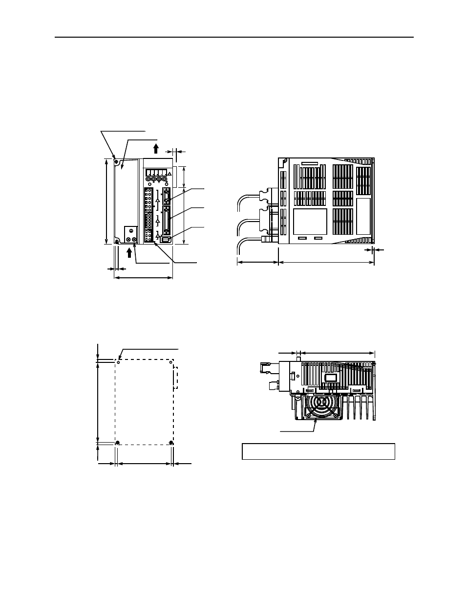
SGDH-15AE (Three-phase, 200V, 1.5kW)
SGDH-05DE to -15DE (Three-phase, 400V, 0.5 to 1.5kW)
8 8 8 8
8
C
N
3
C
N
1
C
N
2
L1
L2
⊕2
⊕1
L1C
L2C
B2
B1
U
V
W
MODE/SET
CHARGE
DATA/
POWER
YASKAWA
SGDH
7.09 (180)
2.95 (75)
0.20 (5)
4.33 (110)
2 x M4 screws
Terminal
block
(3 types)
6.30
(1
60)
Air flow
Air flow
Heat sink
2-
Φ0.20 (Φ5) holes
Mounting Hole Diagram
0.22
2 x M4 screw holes
5.
89 (1
49.5
) ±0.0
20
(0
.5)
(M
ounting pitch)
0.20
(Mounting pitch)
3.94 (100) ±0.020 (0.5)
Cooling fan
Approximate mass: 6.17lb (2.8kg)
0.16 (4)
(5)
5.57 (141.5)
0.28 (7)
0.31 (8)
0.20
(5)
(5.5)
Ground terminal
0.20
(5)
CN3
CN1
CN2
4.17 (
106)
1.54
(39)
Mating connectors: see page 8-43.
See also other documents in the category Yaskawa Equipment:
- Tag Generator (30 pages)
- MP3300iec (82 pages)
- 1000 Hz High Frequency (18 pages)
- 1000 Series (7 pages)
- PS-A10LB (39 pages)
- iQpump Micro User Manual (300 pages)
- 1000 Series Drive Option - Digital Input (30 pages)
- 1000 Series Drive Option - CANopen (39 pages)
- 1000 Series Drive Option - Analog Monitor (27 pages)
- 1000 Series Drive Option - CANopen Technical Manual (37 pages)
- 1000 Series Drive Option - CC-Link (38 pages)
- 1000 Series Drive Option - CC-Link Technical Manual (36 pages)
- 1000 Series Drive Option - DeviceNet (37 pages)
- 1000 Series Drive Option - DeviceNet Technical Manual (81 pages)
- 1000 Series Drive Option - MECHATROLINK-II (32 pages)
- 1000 Series Drive Option - Digital Output (31 pages)
- 1000 Series Drive Option - MECHATROLINK-II Technical Manual (41 pages)
- 1000 Series Drive Option - Profibus-DP (35 pages)
- AC Drive 1000-Series Option PG-RT3 Motor (36 pages)
- Z1000U HVAC MATRIX Drive Quick Start (378 pages)
- 1000 Series Operator Mounting Kit NEMA Type 4X (20 pages)
- 1000 Series Drive Option - Profibus-DP Technical Manual (44 pages)
- CopyUnitManager (38 pages)
- 1000 Series Option - JVOP-182 Remote LED (58 pages)
- 1000 Series Option - PG-X3 Line Driver (31 pages)
- SI-EN3 Technical Manual (68 pages)
- JVOP-181 (22 pages)
- JVOP-181 USB Copy Unit (2 pages)
- SI-EN3 (54 pages)
- SI-ET3 (49 pages)
- MECHATROLINK-III (35 pages)
- EtherNet/IP (50 pages)
- SI-EM3 (51 pages)
- 1000-Series Option PG-E3 Motor Encoder Feedback (33 pages)
- 1000-Series Option SI-EP3 PROFINET (56 pages)
- PROFINET (62 pages)
- AC Drive 1000-Series Option PG-RT3 Motor (45 pages)
- SI-EP3 PROFINET Technical Manual (53 pages)
- A1000 Drive Option - BACnet MS/TP (48 pages)
- 120 Series I/O Modules (308 pages)
- A1000 12-Pulse (92 pages)
- A1000 Drive Software Technical Manual (16 pages)
- A1000 Quick Start (2 pages)
- JUNMA Series AC SERVOMOTOR (1 page)
- A1000 Option DI-101 120 Vac Digital Input Option (24 pages)