Wt u, C data + m, D data − n – Yaskawa Sigma II Series Servo System User Manual
Page 354
Sigma II User’s Manual
Chapter 8: Ratings and Characteristics
8 - 24
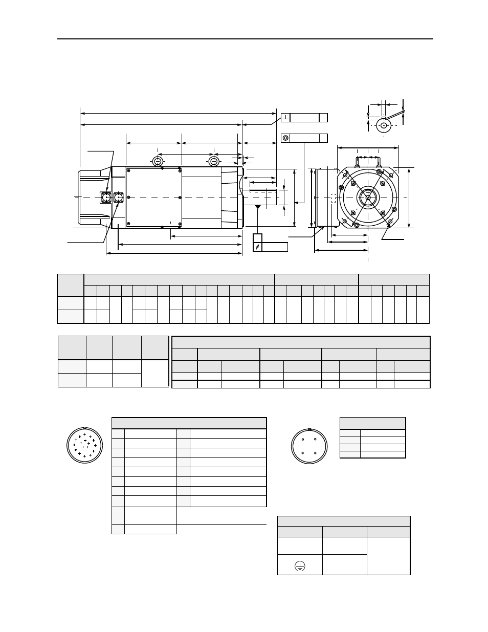
SGMBH Dimensions in inches (mm)
(1) 17 Bit Incremental/Absolute Encoder
Drawings that provide SGMBH servomotor dimensions are shown below.
Note:
1.
Dimensions are the same when using either incremental or absolute encoders.
2.
Tolerances on the dimensions of flange type LB, of shaft extensions S, and of keyway width and depth are based on JIS (Japanese Industrial Standard)
B0401 “Limits and Fits for Engineering.”
Type
SGMBH-
Motor Body Dimensions
Flange Dimensions
Shaft End Dimension
L
LL
LR LD LF
LN
LP KB1 KB2 KG KN KS KT CK1 CK2 J
ΦLA ΦLB** LC LE LG ΦLH ΦLZ ΦS* Q
QK W**** T*** U
2BD A61 29.13
(740)
23.62
(600) 5.51
(140)
9.06
(230)
6.97
(177)
6.30
(160) 4.57
(116)
17.17
(436)
19.06
(484)
8.82
(224) 8.66
(220)
6.42
(163)
5.87
(149)
1.77
(45)
1.77
(45)
9.84
(250)
10.43
(265)
9.06
(230)
9.84
(250)
0.20
(5)
0.79
(20)
11.81
(300)
0.53
(13.5)
2.36
(60)
5.51
(140)
4.33
(110)
0.71
(18)
0.43
(11)
0.28
(7)
3ZD A61 31.91
(810)
26.38
(670)
9.65
(245)
9.06
(230)
19.86
(504)
21.75
(552)
11.50
(292)
A
A
0.0020 (0.05)
0.0020 (0.05)
0.0012 (0.03)
A
W
T
U
Y
Y
Cross-section Y-Y
KT
KS
KN
LC
Q
QK
Φ
S
Φ
LB
J
LC
4 -
ΦLZ
LE
LG
LN
LF
LP
LD
LL
L
KG
KB1
KB2
CK1 CK2
Φ
LH
Φ
LA
Fan connector
Encoder connector
Power wiring
LR
Φ2.40 (Φ61)
Specified Tolerances
Dimension
*
ΦS
**
ΦLB
***T
****W
Unit
Diameter
Tolerance
Diameter
Tolerance
Length
Tolerance
Length
Tolerance
in
2.362
+0.00118 -0.00043 9.055
+0.0000 -0.00181 0.433 +0.0000 -0.00043 0.709 +0.0000 -0.00169
mm
60
+0.030 -0.011
230
+0.000 -0.046
11
+0.000 -0.1103
18
+0.000 -0.043
Type
SGMBH-
Approximat
e Mass
lb (kg)
Allowable
Radial Load
lb (N)
Allowable
Thrust Load
lb (N)
2BD A61
264.5
(120)
1323
(5880)
485
(2156)
3ZD A61
308.7
(140)
1410
(6272)
A
B
C
D
M
N P
T
E
K
G
F
J
S
R
L
H
Encoder Plug
Fan Connector
Receptacle: CE05-2A18-10PD-B
Non-environmental mating connec-
tor: MS3108B18-
10S (L-Type)
Cable Clamp: MS3057-10A
Fan Connector
A
U Phase
B
V Phase
C
W Phase
D
—
A
B
D
C
Power Wiring Terminal Box
Terminal
Connection
Screw Size
U, V, W
Motor
M10
Ground
Non-Environmental Mating Connector:
MS3108B20-29S (L Type)
MS3106B20-29S (Straight Type)
Cable Clamp: MS3057-12A
Connector Wiring on the Encoders
A
—
K
—
B
—
L
—
C Data +
M
—
D Data
−
N
—
E
—
P
—
F
—
R
—
G 0V
S Battery
− (Note*)
H +5V
dc
T
Battery + (Note*)
J
FG (Frame
Ground)
*Note: Used with an absolute
encoder only.