Sequence input circuit interface, Output circuit interfaces – Yaskawa Sigma II Series Servo System User Manual
Page 60
Sigma II User’s Manual
Chapter 3: Wiring
3 - 22
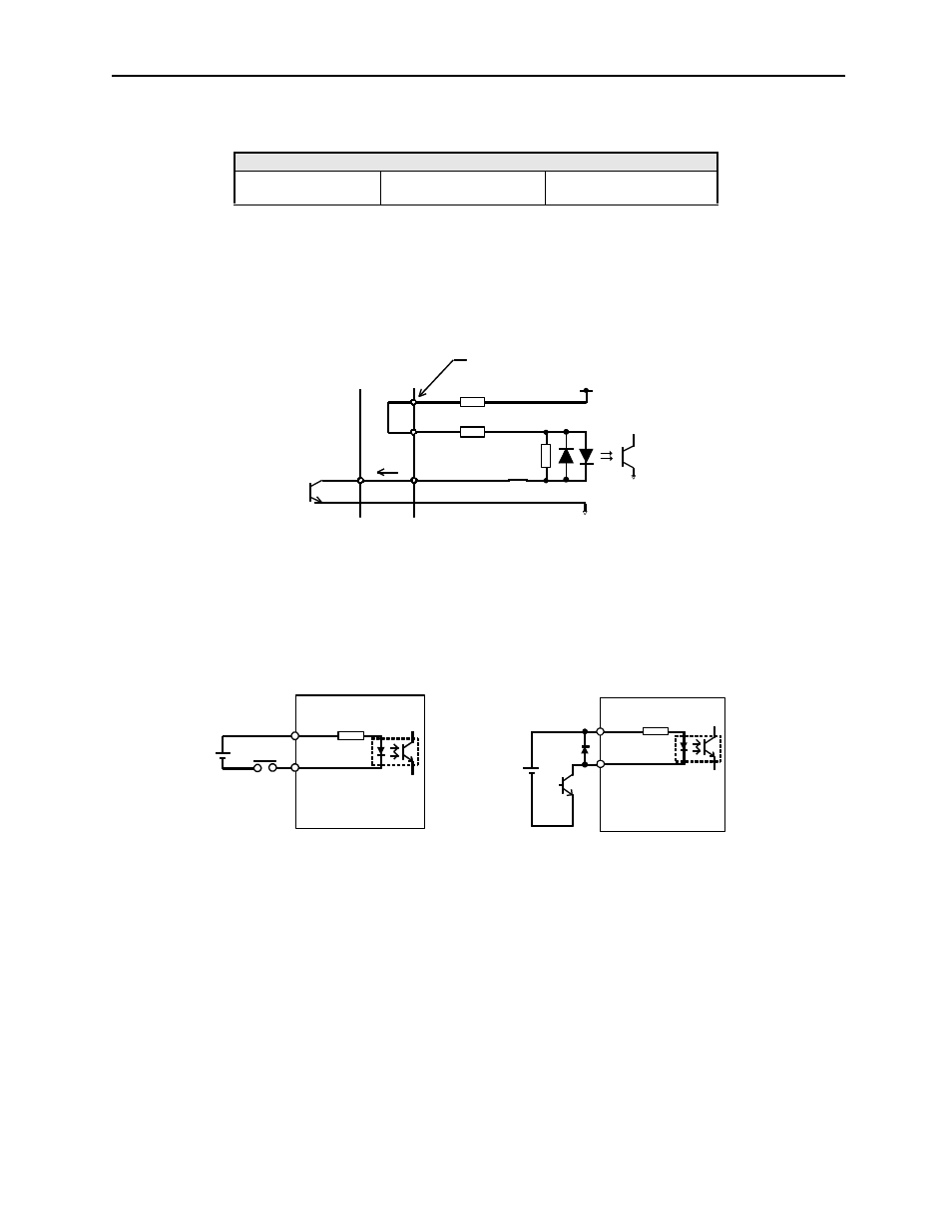
The following examples show how to select the pull-up resistor R1 so the input
current (I) falls between 7 and 15mA.
•
Open-collector Output, Example 2: Using a servo amplifier with an internal 12V
power supply
This circuit uses the 12V power supply built into the servo amplifier. The input
is not isolated in this case.
Sequence Input Circuit Interface
The sequence input circuit interface connects through a relay or open-collector
transistor circuit. Select a low-current relay, otherwise a faulty contact will result.
Output Circuit Interfaces
Any of the following three types of servo amplifier output circuits can be used.
Connect an input circuit at the host controller following one of these types.
•
Connecting to a Line-driver Output Circuit
Encoder serial data converted to two-phase (A and B phase) pulse output signals
(PAO, /PAO, PBO, /PBO), origin pulse signals (PCO, /PCO) and S phase
rotation signals (PCO, /PCO) are output via line-driver output circuits that
normally comprise the position control system at the host controller. Connect
the line-driver output circuit through a line receiver circuit at the host controller.
Application Examples
R1 = 2.2k
Ω with
V
CC
= 24V ±5%
R1 = 1k
Ω with
V
CC
= 12V ±5%
R1 = 180
Ω with
V
CC
= 5V ±5%
PL1, PL2, PL3 terminals
V
1.5V maximum
when ON
About
9mA
Servo amplifier end
Host
controller end
1.0kΩ
150Ω
/S-ON, etc.
Servo amplifier
Servo amplifier
/S-ON, etc.
24V
DC
50mA minimum
24V
DC
50mA minimum
24V
IN
24V
IN
3.3kΩ
3.3kΩ