9 q p ar amet ers with special f u nctions, Example: circular hole patterns – HEIDENHAIN TNC 406 User Manual
Page 231

210
10 Programming: Q Parameters
1
0.9 Q P
ar
amet
ers with Special F
u
nctions
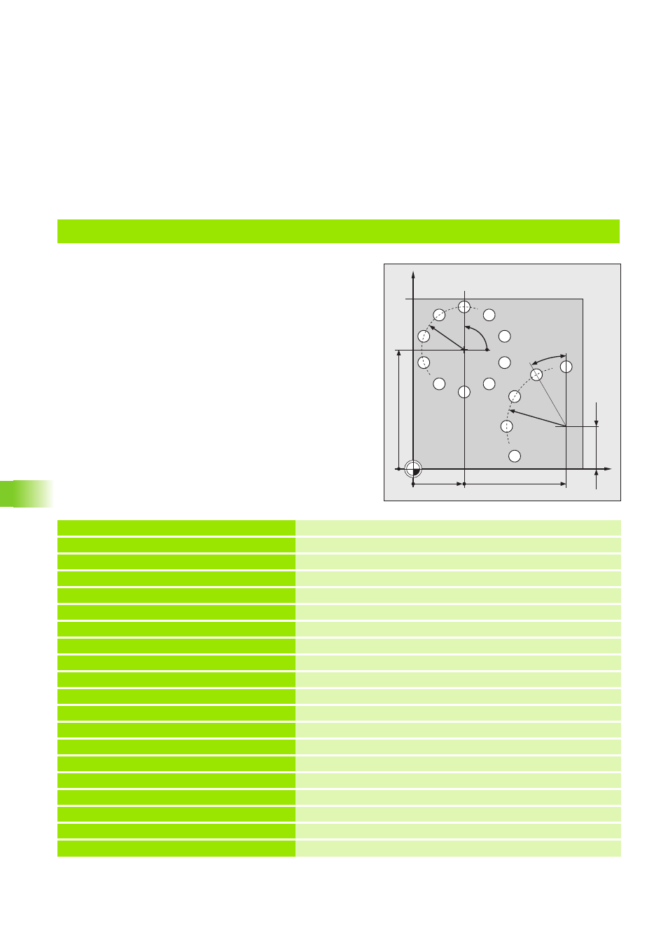
Example: Circular hole patterns
Program sequence
Define parameter coordinates for the full circle
Define parameter coordinates for the circle arc
The positions to be eroded are each approached
in the subprogram LBL1 through movements in
the plane with polar coordinates.
0 BEGIN PGM HOLES MM
1 BLK FORM 0.1 Z X+0 Y+0 Z–20
Define the workpiece blank: MIN point
2 BLK FORM 0.2 X+100 Y+100 Z+0
Define the workpiece blank: MAX point
3 CYCL DEF 1.0 GENERATOR
Cycle GENERATOR (see ”Cycle 1 GENERATOR” on page 133)
4 CYCL DEF 1.1 P-TAB 300
Select erosion table (here, table 300)
5 CYCL DEF 1.2 MAX=12 MIN =12
Set power stage (here, to stage 12)
6 TOOL DEF 1 L+0 R+5
Define electrode in the program
7 TOOL CALL 1 Z U+1
Call electrode in the infeed axis Z, undersize 1 mm
8 L Z+100 R0 F MAX M
Retract in the infeed axis; rapid traverse; insert electrode
9 FN 0: Q1 = +30
Full circle 1: center X
10 FN 0: Q2 = +70
Full circle 1: center Y
11 FN 0: Q3 = +10
Full circle 1: number of cavities
12 FN 0: Q4 = +25
Full circle 1: radius
13 FN 0: Q5 = +90
1 and 2: starting angle
14 FN 0: Q6 = +0
Full circle 1: angle increment (input value 0: full circle)
15 FN 0: Q7 = +2
1 and 2: set-up clearance
16 FN 0: Q8 = –15
1 and 2: eroding depth
17 CALL LBL 1
Call subprogram 1 for full circle
X
Y
30
90
1
2
25
35
25
70
90°
30°
