5 coor dinat e t ransf or mation cy cles – HEIDENHAIN TNC 406 User Manual
Page 191
170
8 Programming: Cycles
8.5 Coor
dinat
e
T
ransf
or
mation Cy
cles
WORKING PLANE cycle in a part program:
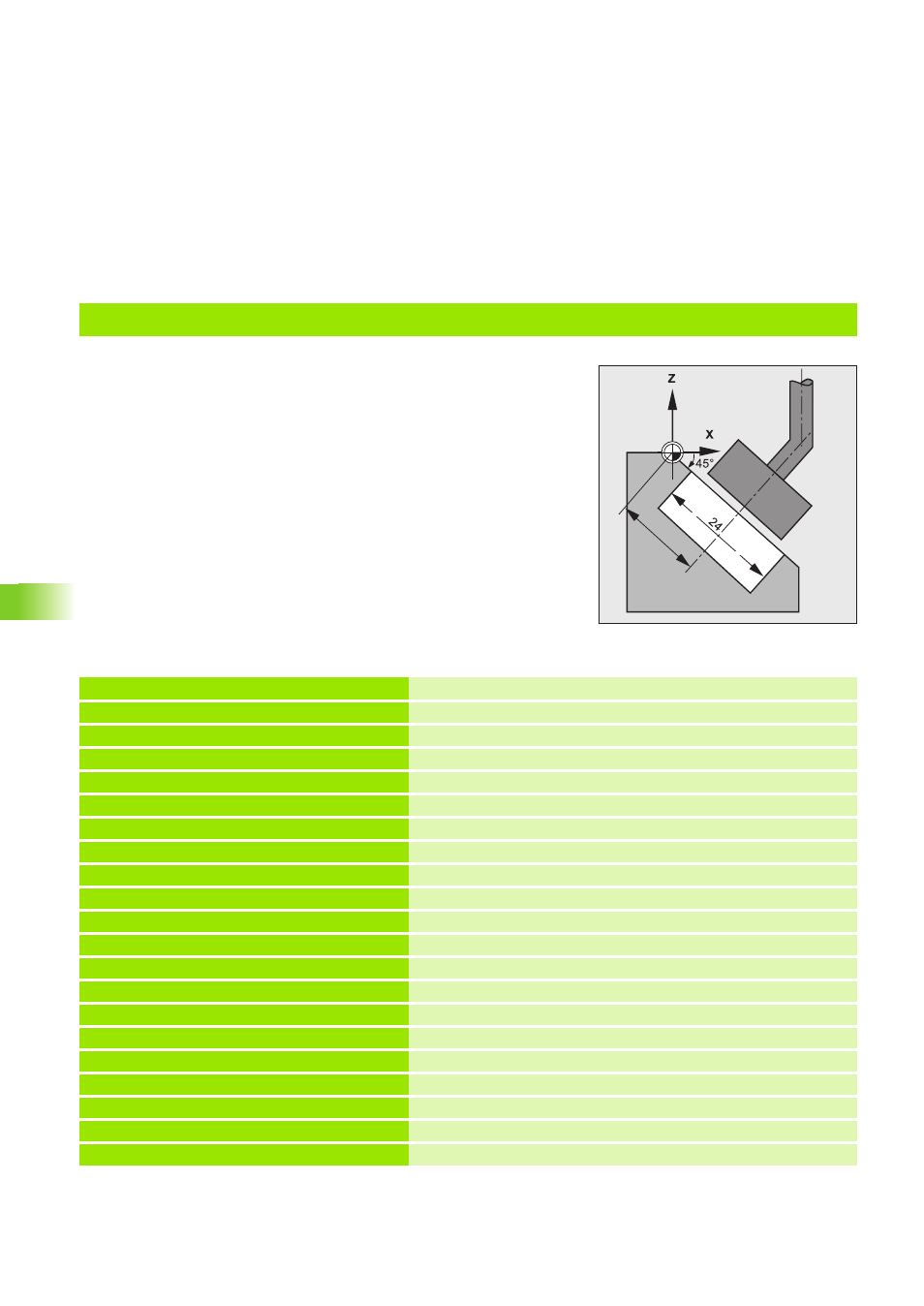
Practice examples: Tilt the working plane with Cycle 17 DISK
Execute disk cycle with 45° tilt in the B axis,
depth = 10 mm.
For calculation of the cycle parameters,
see example Cycle DISK.
20
0 BEGIN PGM CYC19 MM
1 BLK FORM 0.1 Z X+0 Y+0 Z–40
2 BLK FORM 0.2 X+100 Y+100 Z+0
3 CYCL DEF 1.0 GENERATOR
Cycle GENERATOR (see ”Cycle 1 GENERATOR” on page 133)
4 CYCL DEF 1.1 P-TAB 100
Desired erosion table
5 CYCL DEF 1.2 MAX=7 MIN=7
Select power stage
6 TOOL DEF 1 L+0 R+9.9
Define the tool
7 TOOL CALL 1 Z U+4.2
Tool call
8 L Z+100 R0 F MAX
Pre-position to set-up clearance
9 CYCL DEF 19.0 WORKING PLANE
Define Cycle 19 WORKING PLANE
10 CYCL DEF 19.1 B+45
Tilt working plane about the B axis
11 L X+20 Y+20 R0 F MAX M
Pre-position to center of disk
12 L Z+1 R0 F MAX M
Pre-position over the workpiece surface
13 CYCL DEF 17.0 DISK
Define Cycle 17 DISK
14 CYCL DEF 17.1 Z–10 M36
Eroding depth Z = –10 mm, eroding ON
15 CYCL DEF 17.2 RAD=2 MOD=0
Expansion radius RAD = 2 mm, circular expansion
16 L Z+50 F MAX M37 M
Retract diagonally to safety clearance, eroding OFF
17 CYCL DEF 19.0 WORKING PLANE
Reset Cycle 19 WORKING PLANE
18 CYCL DEF 19.1 B+0
19 L R F M2
20 END PGM CYC19 MM