4 er osion cy cles, Practice examples: eroding with cycle 16 orbit – HEIDENHAIN TNC 406 User Manual
Page 171

150
8 Programming: Cycles
8.4 Er
osion Cy
cles
Cycle 16 ORBIT in the part program, example 1
Practice examples: Eroding with Cycle 16 ORBIT
Workpiece geometry
Cavity diameter D = 24 mm
Eroding depth T = –10 mm
Electrode data
Cylindrical electrode
Electrode radius Re = 9.9 mm
Electrode undersize U = 4.2 mm
Determining the eroding gap B through indexed
assignment
Calculation of the expansion radius
Expansion radius for Cycle 16 ORBIT
RAD = 0.5 • (UM – UNS)
RAD = 0.5 • D – Re – 0.5 • UNS
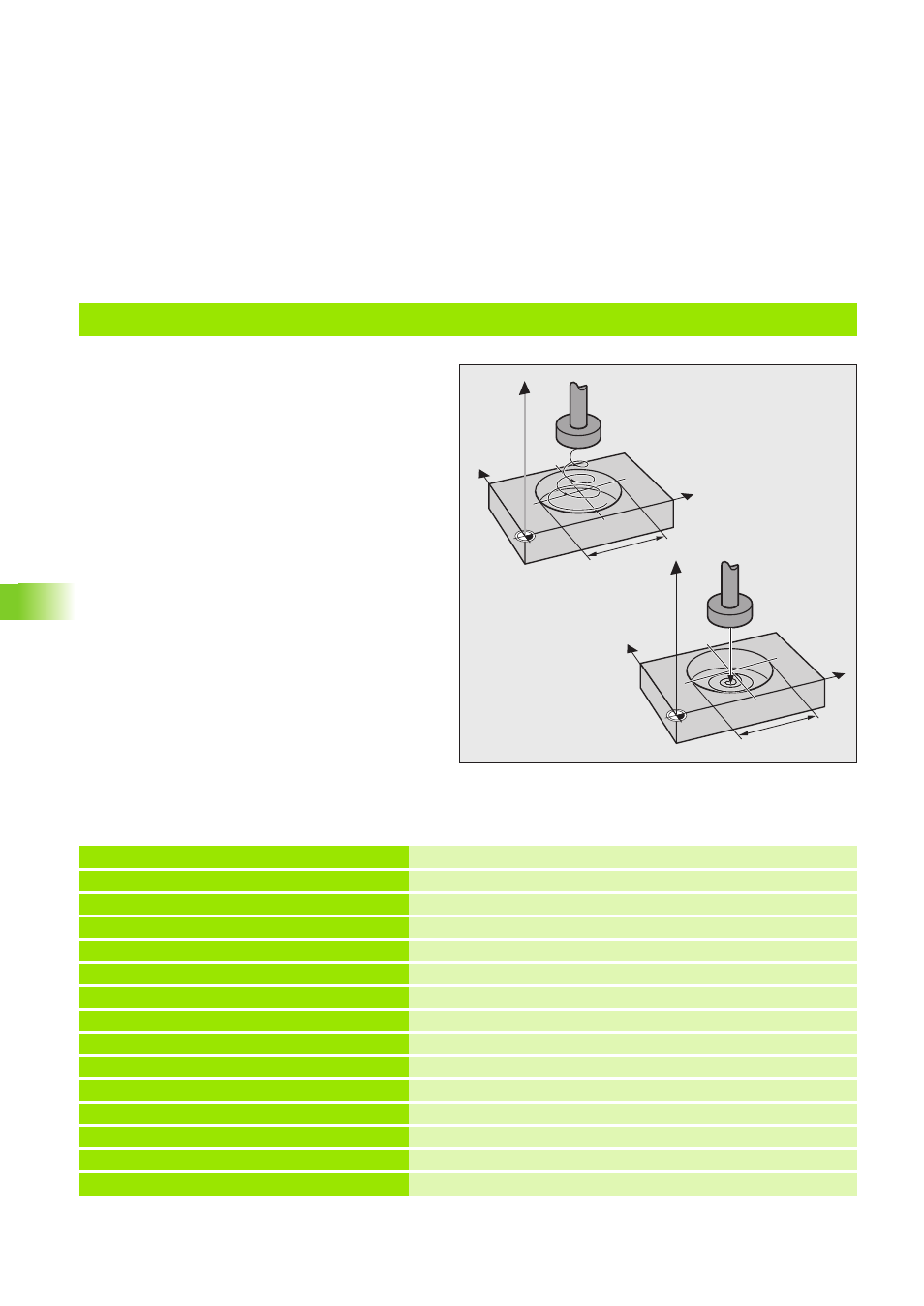
Example 1, top illustration:
Pre-position over the workpiece surface, circular
expansion.
Example 2, bottom illustration:
Erode to –10 mm depth, circular expansion
without pecking.
Y
X
Z
24 mm
Y
X
Z
24 mm
0 BEGIN PGM EX1 MM
1 BLK FORM 0.1 Z X+0 Y+0 Z–20
2 BLK FORM 0.2 X+100 Y+100 Z+0
3 CYCL DEF 1.0 GENERATOR
Cycle GENERATOR (see ”Cycle 1 GENERATOR” on page 133)
4 CYCL DEF 1.1 P-TAB CUST1
Desired erosion table
5 CYCL DEF 1.2 MAX=10 MIN=5
Maximum power stage = 10, minimum power stage = 5
6 TOOL DEF 1 L+0 R+9.9
Electrode radius
7 TOOL CALL 1 Z U+4.2
Undersize
8 L Z+50 C+0 R0 F MAX M37
Pre-position to set-up clearance, eroding OFF
9 L X+50 Y+50 Z+1 R F MAX
Pre-position over the workpiece surface
10 FN 0: Q1 = +11
Assign incremental depth to Q1
11 LBL1
Label number
12 FN16: Q10 = Q200(Q99)
The diametrical gap according to the current power stage is
assigned to Q10 (see ”Indexed assignment” on page 198)
13 FN2: Q9 = +Q158 - +Q10
Electrode undersize UM minus electrode undersize UNS
