4 er osion cy cles, Example for cycle 14 contour geometry – HEIDENHAIN TNC 406 User Manual
Page 169
148
8 Programming: Cycles
8.4 Er
osion Cy
cles
Main program:
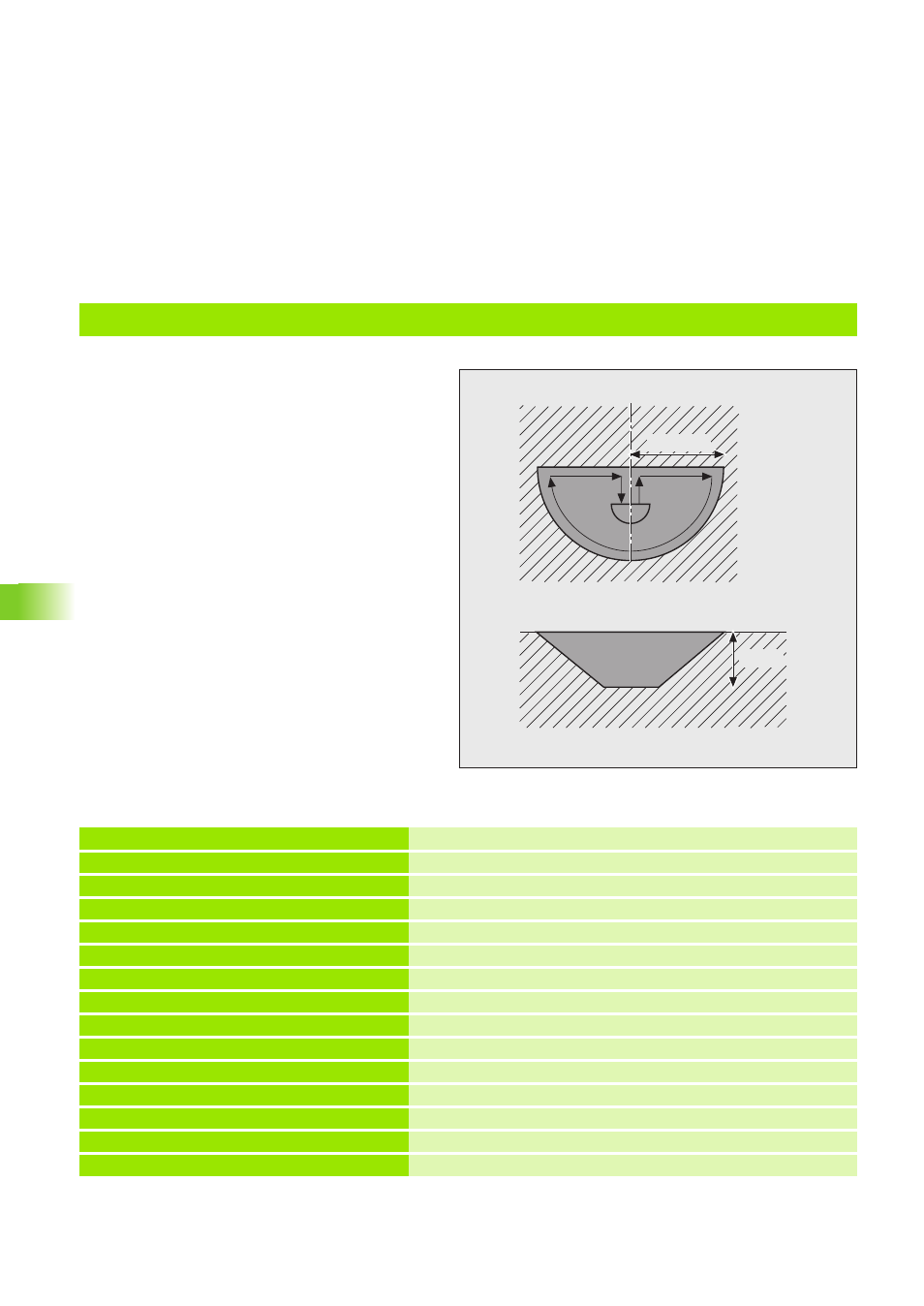
Example for Cycle 14 CONTOUR GEOMETRY
The program GEOMETR describes the geometry
of the contour.
The program is called through Cycle 14 CONTOUR
GEOMETRY.
The form electrode moves into the material step-
by-step according to counting parameter Q5.
The scaling factor is decreased after each infeed,
resulting in the diagonal side wall.
Machine parameter MP7410=1, meaning the
scaling factor does not apply to the Z axis.
r = 25 mm
12 mm
0 BEGIN PGM POCKET MM
Start of program
1 BLK FORM 0.1 Z X-50 Y-50 Z-30
Define the workpiece blank
2 BLK FORM 0.2 X+50 Y+50 Z+0
3 CYCL DEF 1.0 GENERATOR
Cycle GENERATOR (see ”Cycle 1 GENERATOR” on page 133)
4 CYCL DEF 1.1 P-TAB HDH700
Select erosion table (here, table HDH700)
5 CYCL DEF 1.2 MAX=13 MIN=13
Select power stage 13
6 TOOL DEF 1 L+0 R+3
Define the tool
7 TOOL CALL 1 Z U+0
Tool call
8 L Z+50 C+0 R F M37
Set-up clearance, orient electrode, eroding OFF
9 L X+0 Y+0 Z+1 R F M
Pre-positioning
10 FN 0: Q5 = +8
Counting parameter
11 FN 0: Q1 = +1
Scaling factor
12 FN 0: Q10= +25
Contour radius (semicircle)
13 FN 4: Q12= +Q10 DIV +2
Auxiliary parameters for pre-positioning in Y direction
14 FN 0: Q4 = +80
Parameter for spark-out distance in percent