9 q p ar amet ers with special f u nctions, Example: ellipse – HEIDENHAIN TNC 406 User Manual
Page 229
208
10 Programming: Q Parameters
1
0.9 Q P
ar
amet
ers with Special F
u
nctions
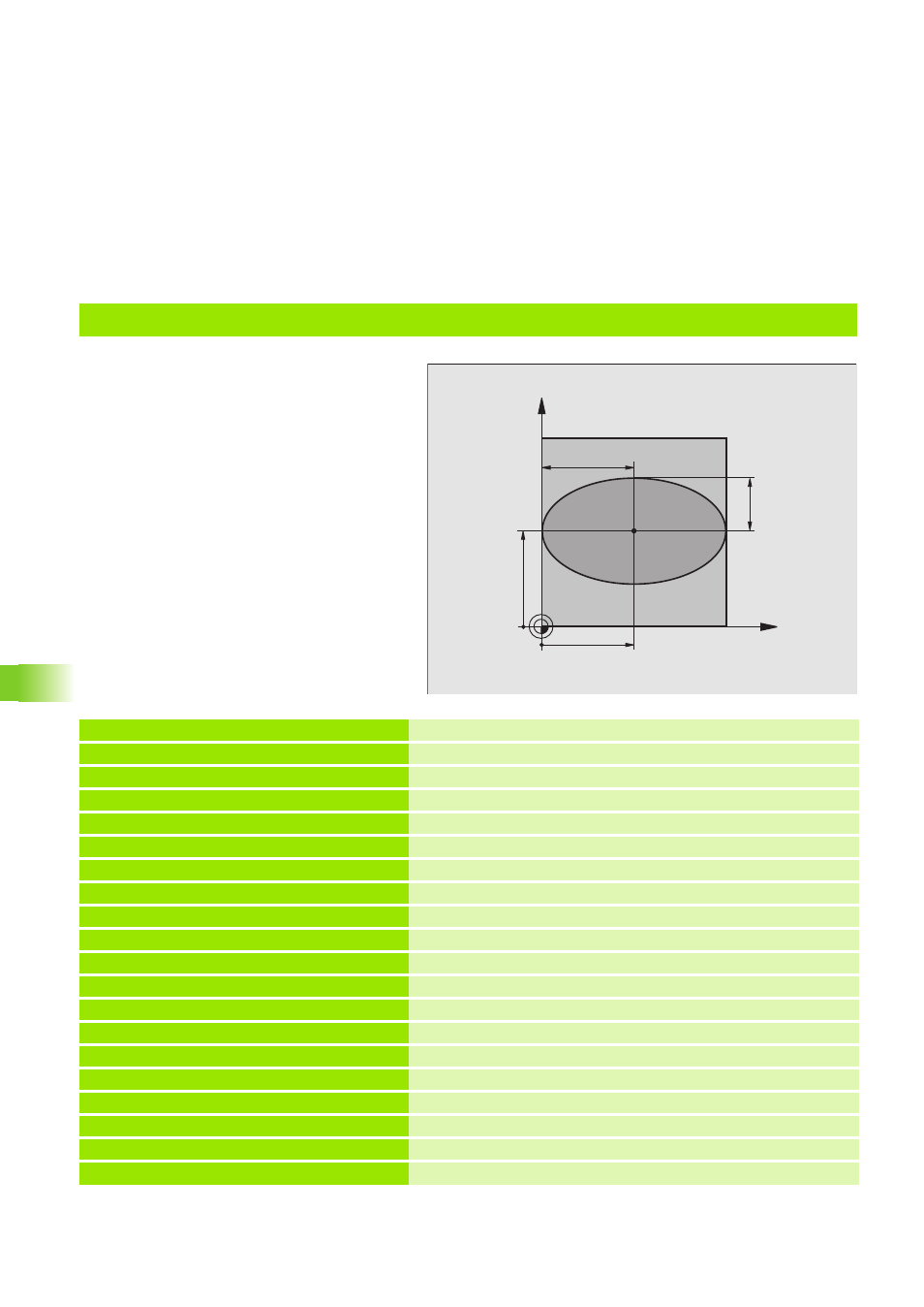
Example: Ellipse
Program sequence
The contour of the ellipse is approximated by
many short lines (defined in Q7). The more
calculating steps you define for the lines, the
smoother the curve becomes.
The machining direction can be altered by
changing the entries for the starting and end
angles in the plane:
Clockwise machining direction:
starting angle > end angle
Counterclockwise machining direction: starting
angle < end angle
The tool radius is not taken into account.
0 BEGIN PGM ELLIPSE MM
1 FN 0: Q1 = +50
Center in X axis
2 FN 0: Q2 = +50
Center in Y axis
3 FN 0: Q3 = +50
Semiaxis in X
4 FN 0: Q4 = +30
Semiaxis in Y
5 FN 0: Q5 = +0
Starting angle in the plane
6 FN 0: Q6 = +360
End angle in the plane
7 FN 0: Q7 = +40
Number of calculating steps
8 FN 0: Q8 = +0
Rotational position of the ellipse
9 FN 0: Q9 = +5
Milling depth
10 FN 0: Q10 = +100
Feed rate for plunging
11 FN 0: Q11 = +350
Feed rate for milling
12 FN 0: Q12 = +2
Setup clearance for pre-positioning
13 BLK FORM 0.1 Z X+0 Y+0 Z-20
Define the workpiece blank
14 BLK FORM 0.2 X+100 Y+100 Z+0
15 CYCL DEF 1.0 GENERATOR
Cycle GENERATOR (see ”Cycle 1 GENERATOR” on page 133)
16 CYCL DEF 1.1 P-TAB 300
Select erosion table (here, table 300)
17 CYCL DEF 1.2 MAX=12 MIN=8
Power stages, for example between 8 and 12
18 TOOL DEF 1 L+0 R+5
Define electrode in the program
19 TOOL CALL 1 U+1
Call electrode in the infeed axis Z, undersize 1 mm
X
Y
50
50
30
50