Working plane (cycle 19), 5 coor dinat e t ransf or mation cy cles – HEIDENHAIN TNC 406 User Manual
Page 182
HEIDENHAIN TNC 406, TNC 416
161
8.5 Coor
dinat
e
T
ransf
or
mation Cy
cles
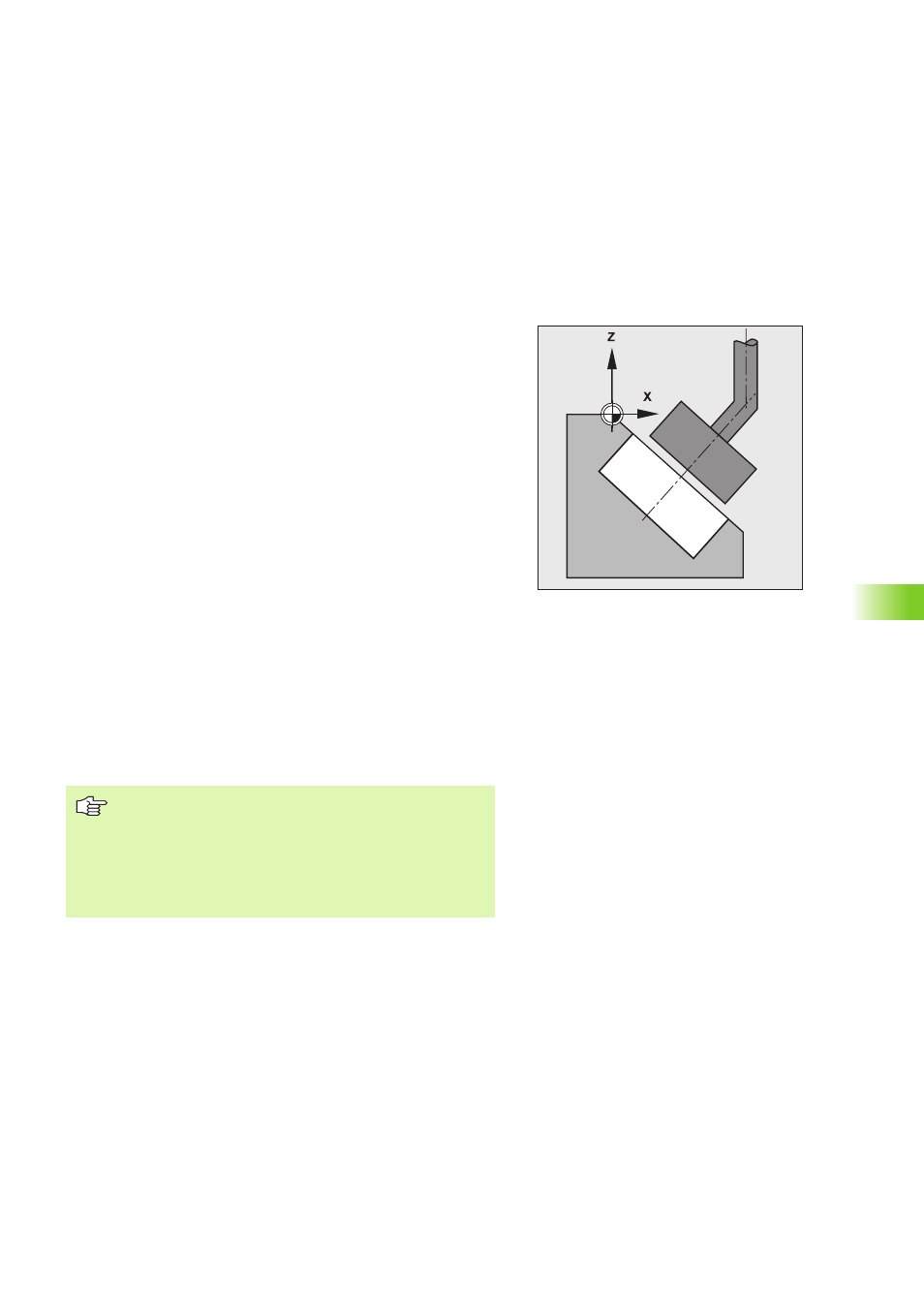
WORKING PLANE (Cycle 19)
Function
With Cycle 19, it is possible to tilt linear traverse and machining with
Cycle 16 ORBIT, Cycle 17 DISK or an OEM cycle at random in a 3-D
plane. Thus, execution of inclined eroding-cycles can be made simple.
Effect
After a cycle definition WORKING PLANE, the TNC tilts the
subsequent machining blocks around the datum which was last set in
the MANUAL mode (active datum).
Input
You enter:
Tilt angle A, corresponding to the rotation about the X axis. This can
be programmed with the orange key X.
Tilt angle B, corresponding to the rotation about the Y axis. This can
be programmed with the orange key Y.
Tilt angle C, corresponding to the rotation about the Z axis. This can
be programmed with the orange key Z.
The TNC displays the current active tilt angles in the STATUS TILT
display.
Input range: –360° to +360° (only absolute values possible).
Cancellation
To cancel the tilt angle, redefine the WORKING PLANE cycle and enter
an angular value of 0° for all axes of rotation, or select a new program.
Coordinate transformations, e.g. a datum shift, are also
effective when the Tilt working plane function is active.
An active basic rotation is calculated in the same way as
a tilting of the machine plane about the C axis.
When creating OEM cycles, remember that traverse
paths within the cycle may only be programmed with L
blocks.