5 coordinate transformation cycles, Cycles for electrode definition, Coordinate transformation cycles – HEIDENHAIN TNC 406 User Manual
Page 176

HEIDENHAIN TNC 406, TNC 416
155
8.5 Coor
dinat
e
T
ransf
or
mation Cy
cles
8.5 Coordinate Transformation
Cycles
Cycles for electrode definition
You can enter electrode data in this cycle in a manner similar to the NC
function TOOL DEF.
In addition, you can program an electrode compensation in up to four
axes.
Coordinate transformation cycles
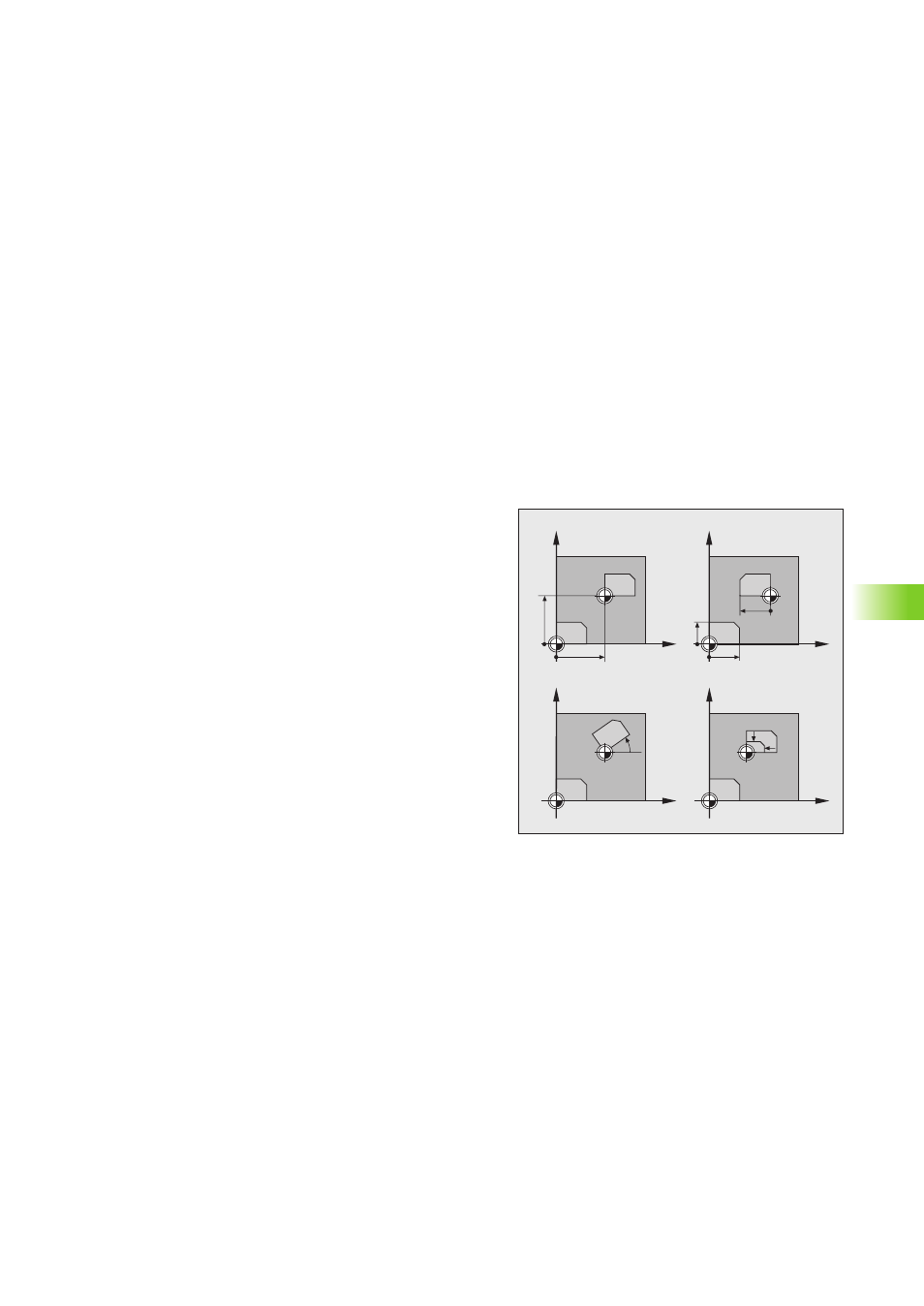
Once a contour has been programmed, you can position it on the
workpiece at various locations and in different sizes through the use
of coordinate transformations.
For example you can
Move a contour: DATUM SHIFT (Cycle 7)
Mirror a contour: MIRROR IMAGE (Cycle 8)
Rotate a contour: ROTATION (Cycle 10)
Reduce or increase the size of a contour: SCALING FACTOR (Cycle
11)
The original contour must be marked in the main part program as a
subprogram or program section repeat.
In addition, the function ”Tilt working plane” can be used to execute
Cycle 16 ORBIT, Cycle 17 DISK or an OEM cycle in a tilted system of
coordinates.
Canceling coordinate transformations
You can cancel a coordinate transformation in the following ways:
Define cycles for basic behavior with a new value, such as scaling
factor 1.0
Execute the miscellaneous function M02 or M30, or an END PGM
block (depending on machine parameters)
Select a new program
Y
X
Y
X
Y
X
Y
X
