4function description, 4 expansion cards, Example for networking two pmctendo dd5 – Pilz PMCtendo DD5.03/000/0/0/0/110-230VAC User Manual
Page 71: Can1, connector x6b: can master
Pilz GmbH & Co. KG, Felix-Wankel-Straße 2, 73760 Ostfildern, Germany
Telephone: +49 711 3409-0, Telefax: +49 711 3409-133, E-Mail: [email protected]
4-43
4.4
Expansion cards
4
Function description
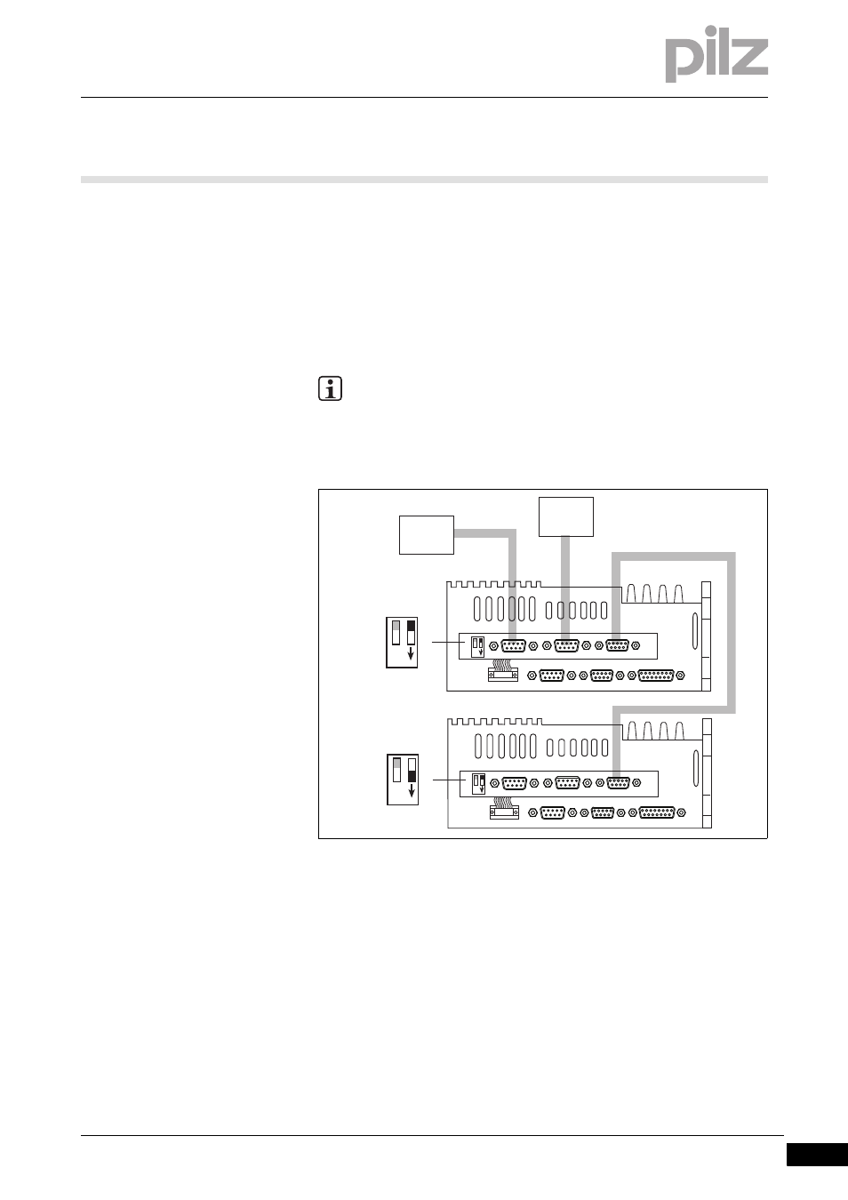
Example for networking two PMCtendo DD5:
PC connected to the first PMCtendo DD5 connector X6A
PMCtendo DD5 connector X6 linked with fieldbus adapter
CAN1, connector X6B: CAN Master
CAN2: Socket X6C: Connection between the two PMCtendo DD5
Terminating resistor on the last PMCtendo DD5 selected: CAN-Term
switch = 1 (ON)
Fig. 4-15:
Networking two PMCtendo DD5
INFORMATION
Details of the connector pin assignment are available in Chapter
8, "Wiring" in the section entitled "Fieldbus junction box".
X1
X2
X5
X6
X6A
X6B
X6C
RS 232
CAN1
CAN2
Feed
CAN-T
erm
ON
Feed
CAN-T
erm
ON
PC
CAN
Master
X1
X2
X5
X6
X6A
X6B
X6C
RS 232
CAN1
CAN2
Feed
CAN-T
erm
ON
Feed
CAN-T
erm
ON
CAN-Term = OFF
CAN-Term = ON