3 connection example, 4 analogue inputs, 4function description – Pilz PMCtendo DD5.03/000/0/0/0/110-230VAC User Manual
Page 45: 3 control element
Pilz GmbH & Co. KG, Felix-Wankel-Straße 2, 73760 Ostfildern, Germany
Telephone: +49 711 3409-0, Telefax: +49 711 3409-133, E-Mail: [email protected]
4-17
4.3
Control element
4
Function description
4.3.3.3
Connection example
Connection example
4-
][Funktion_STO_Beispiel_einkanalig_1
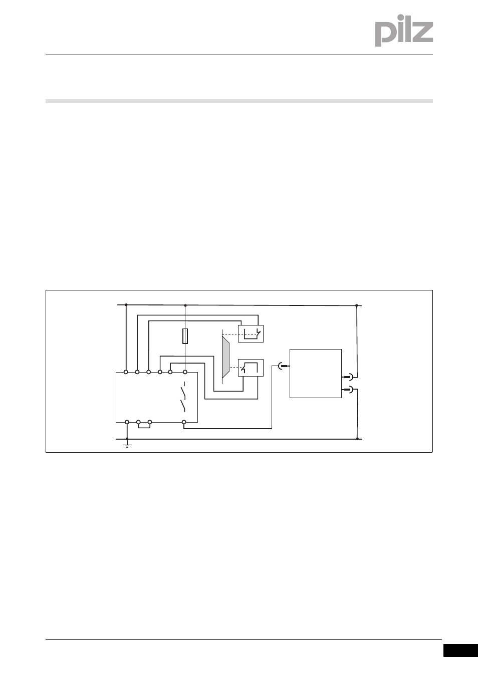
The following circuit example illustrates single-channel activation of the
safety function STO.
The drives are switched via a safety gate.
Safety gates S1/S2 are monitored by a safety relay PNOZ s3.
Shorts across contacts are detected.
The safety relay is wired for an automatic reset.
The safety function STO complies with PL d (Cat. 2) of EN ISO 13849-
1 and SIL CL 2 of EN/IEC 62061.
The relays' wiring must comply with the category or performance level
required for the application. Further information on the safety relays is
available from Pilz.
][Funktion_STO_Beispiel_einkanalig_2_DD5
Fig. 4-7:
STO with safety relay PNOZ s3
4.3.4
Analogue inputs
Analogue inputs
4-
][Funktion_Ein_analog_DD5
Functions:
The servo amplifier has 2 analogue voltage inputs (ANALOG-IN1, AN-
ALOG-IN2) for specifying setpoint values.
Differential inputs, signal range from -10 VDC to +10 VDC.
Resolution (with sign bit):
– Input ANALOG-IN1: 14 Bit
– Input ANALOG-IN2: 12 Bit
PNOZ s3
A1 S11
STO-ENABLE
S12 S21 S22 23
24
S12 S34
A2
X4
24V
0V
24 V
0 V
S1
S2
5
1
3
Servo Drive