3 external brake resistor, 6wiring, 6 power element – Pilz PMCtendo DD5.03/000/0/0/0/110-230VAC User Manual
Page 109
Pilz GmbH & Co. KG, Felix-Wankel-Straße 2, 73760 Ostfildern, Germany
Telephone: +49 711 3409-0, Telefax: +49 711 3409-133, E-Mail: [email protected]
6-19
6.6
Power element
6
Wiring
6.6.3
External brake resistor
External brake resistor
6-
][Verdr_Leiterquerschnitte_Verweis
Under “Connection cables”, please note the requirements for the:
Cable cross sections
Insulation material
][Verdr_Bremse_extern_DD5
Use the following fuses for F
B1
and F
B2
, depending on the device type.
US types in brackets
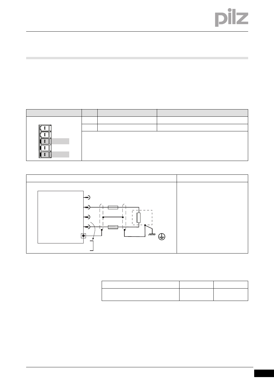
Connector pin assignment
Connector X8
Pin
Designation
Description
3
+RBext
Connection of external brake resistor +
5
-RB
Connection of external brake resistor -
Connection
Output circuit
Motor with brake
Internal brake resistor:
Link Pin 4 (+RBint) and Pin 5 (-RB)
External brake resistor:
Remove the link between Pin 4
(+RBint) and Pin 5 (-RB)
Fuse
Device type
1.5 A, 3 A
6 A, 10 A
Blow-out fuse or similar
6 AT
(FRS-6)
6 AT
(FRS-10)
X8
1 -DC
3 +RBext
4 +RBint
5 -RB
2 n.c.
1
3
Servo Drive
X8
-DC
4
5
+RBint
RBe
+RBext
-RB
FB1
FB2