4function description, 3 control element – Pilz PMCtendo DD5.03/000/0/0/0/110-230VAC User Manual
Page 59
Pilz GmbH & Co. KG, Felix-Wankel-Straße 2, 73760 Ostfildern, Germany
Telephone: +49 711 3409-0, Telefax: +49 711 3409-133, E-Mail: [email protected]
4-31
4.3
Control element
4
Function description
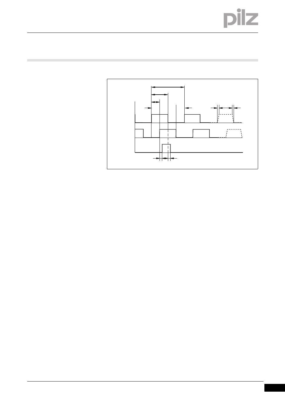
Timing diagram for the incremental encoder signal:
a: Edge spacing
≥
0.2
μ
s
tv: Edge steepness
≤
0.1
μ
s
NI – td: Delay
≤
0.1
μ
s
|
Δ
U|
≥
2 V/20 mA
Default count direction: Upwards, facing the motor axis when rotating
clockwise
][Funktion_Encoder_Emu_SSI
Output of SSI signals
Functions:
With this encoder emulation, positional data for the SSI interface is pre-
pared from the existing output signals from the resolver or SinCos en-
coder.
A max. 32 Bits are transferred.
Single-turn: The leading 12 to 16 Bits are zero, the following 16 Bits
indicate the position. On 2-pole resolvers the position value refers to
a full revolution of the motor; on 4-pole resolvers it refers to half a rev-
olution and on 6-pole resolvers to one third of a revolution.
Multi-turn: The leading 12 to 16 Bits indicate the number of revolu-
tions; the following 16 bits state the position.
A
B
NI
5 V
5 V
5 V
a
a
a
a
tv
tv
td
td
90°
180°
360°